RTK and general GNSS inaccuracies

I have some questions presented to me that I cannot answer adequately and as they relate to the RTK accuracy that we are striving for I thought it appropriate to ask here.

Some prelim analysis on Mission Planner/Pixhawk system

  1.  Septentrio logs and sends at 10 Hz – Mission Planner logs at 4 hz. Even though it records 8 records per second they are doubles (repeating coords). Does Mission Planner actually do 10Hrz?
    

Mission Planner Log
image005.jpg

  1.  Mission Planner only records cords to 7 decimal places. This is only accurate to about 1.5cm. Need to record Degrees to 9 decimal places if it wants to be survey grade and RTK able.
    
  2.  There is an offset being introduced in Mission Planner to the coordinates in an easterly direction by about 20cm. This needs to be fixed as not survey grade or RTK useable for centimetre accuracy. (see Pic)
    

Question! if we have a super duper GNSS that does multipath checking and Ionosphere attenuation corrections with its own well developed EKF filters that can detect whether or not the gps can supply RTK, Float, dGPS to GPS on no positional at all. Wy can’t we just tell mission planner that what is getting is as good as it gets and all it needs to do is monitor the position type and is loss of GPS all together then check for the other GPS units (triple redundant). Main GNSS is survey grade Septentrio. This makes sense to me why try to reinvent the wheel when someones already built one to works on a Ferrari?

As more RTK systems are coming onto the market this has raised some pertinent issues.
Working towards sub 1cm accuracy is impossible on Ardupilot/Mission Planner is it only records to 7 decimal places.
Does it?
Can we get 9 decimal places from Mission Planner?
Or is it an Ardupilot short coming?

Mission_Planner_Septentrio_Tests_20161111.pdf (122.8 KB)

MP is recording the telemetry log, this is controlled by the streamrates which will need to be raised to get 10Hz data from it. However if the selected streamrates are to fast for the baudrate on the telemetry port the data rates will be retarded until the system has balanced the streamrate needs. However you shouldn’t be relying on the tlog for this purpose as data can be dropped quite easily or lost to a momentary radio problem. The telemetry log is recorded as a int32_t, when you are looking at the conversion to a csv it simply did int32_t / 1e7 which is where the double came from. If you were to parse the tlog directly you can avoid this problem.

The MAVLink spec is only good to 7 decimal places, http://mavlink.org/messages/common#GPS_RAW_INT ArduPilot is also only storing 7 decimal places internally.

I can’t really comment on the offset directly, are you looking at the GPS_RAW_INT or the GLOBAL_POSITION_INT message? The former is the GPS position, the latter is the result of the GPS fused with EKF.

The last comment in there is confusing. I assume you (and or the orginal question author) are actually referring to on the aircraft rather then MP?

what options have you set for the ekf? regarding gps intergration? can you provide your param file?

the ekf is a fusion of gps, accel, gyro, etc. so depending on the noise factors and the ekf settings the ekf position can vary based on many variables.

I have not played with any EKF settings as I have no idea what I might be doing in there.

Here are the Octo Logs and the SBF logs.

We do not bother at all with telemetry logs.
The only logs I have used in the past has been the Dataflash logs.

Now it looks like the AsteRx-m logs might be the only usable logs but it seems as the RTK is coming through Mission Planner and then Ardupilot, the GNSS corrections of co-ordinates are being truncated to 7 decimal places, which is not of much use.

The offset has been explained to me but this is where it gets above my head:

If the Pixhawk only uses the GPS ellipsoid height from WGS84 datum, Mission Planner may need to implement AusGeoid09 to calculate AHD.

Some shit on AHD here
AGRS tools, models and resources | Geoscience Australia
download of grid file at bottom of page.

And there are other corrections that may not be taken into account.

Some prelim analysis on Mission Planner/Pixhawk system

  1.  Septentrio logs and sends at 10 Hz – Mission Planner logs at 4 hz. Even though it records 8 records per second they are doubles (repeating coords). Does Mission Planner actually do 10Hrz?
    

Mission Planner Log

  1.  Mission Planner only records cords to 7 decimal places. This is only accurate to about 1.5cm. Need to record Degrees to 9 decimal places if it wants to be survey grade and RTK able.
    
  2.  There is an offset being introduced in Mission Planner to the coordinates in an easterly direction by about 20cm. This needs to be fixed as not survey grade or RTK useable for centimetre accuracy.
    

Question! if we have a super duper GNSS that does multipath checking and Ionosphere attenuation corrections with its own well developed EKF filters that can detect whether or not the gps can supply RTK, Float, dGPS to GPS on no positional at all. Wy can’t we just tell mission planner that what is getting is as good as it gets and all it needs to do is monitor the position type and is loss of GPS all together then check for the other GPS units (triple redundant). Main GNSS is survey grade Septentrio. This makes sense to me why try to reinvent the wheel when someones already built one to works on a Ferraris?

As the movement towards readily available RTK gathers pace we are going to have to improve this accuracy.

Is there a plan for a future builds of mission planner and ardupilot that addresses these limitations? I am in the process of integrating an RTK reciever. Precision surveying is core to our business offering.

I’m a little confused as to what the end goal is? ie relying on the gps to log full precision, and use the trigger inputs on the gps. or use the pixhawk, using seconds hand info that the gps can capture.

Currently ArduPilot does not maintain the accuracy internally to go sub cm. all units are either float, or number * 1e7
refering to https://en.wikipedia.org/wiki/Decimal_degrees
means that we are at decimal places 7, for the 1e7’s
however, the ekf operates on floats.
refering to https://en.wikipedia.org/wiki/Floating_point#Internal_representation
means we roughly have ~7.2 decimal digits of precision.

NOTE floats are ~7.2 digits, 1e7 is 7 decimal places. (float = 123.1234, 1e7 = 123.1234567)

So at this point in time, you can not rely on the pixhawk to provide that level of accuracy. You can rely on the gps’s input triggers and logging however.

I’m not aware of any current plan to switch to doubles internally, which would resolve this issue.

hopefully this answers your questions.

Michael,

Thanks for the links and information.

I can life with 11.132mm for my current application. However, I do have GNSS receiver capable of 2mm of accuracy. Eventually, I’d like to get this working with Ardupilot. What is the best way to put in a request for doubles internally. Seems like a new RTK receiver is being launched every other month, so I am guessing this would be valued by many using ardupilot.

And to make sure I understand your comments, GPS trigger and logging are not subject to the limitations of 1e7s. I assume this means the logged GPS values are raw data? Is that correct?

Thanks,
Dave

@skyveyor Depends by where you mean logged. On Septentrio it’s logging it’s own format. ArduPilot does not log raw messages from the GPS, rather it logs it’s own internal summary of the GPS status. For more details on whats logged scroll down to the GPS entry on: http://ardupilot.org/copter/docs/common-downloading-and-analyzing-data-logs-in-mission-planner.html

What this means is that any detail you ever extract from an Ardupilot log will be limited to 1e7.

@WickedShell We do only use the Septentrio logs, due to this lack of decimal accuracy, but unfortunately, the way RTK is done on Ardupilot is by injecting the RTK signal through Mission Planner to Ardupilot which then routes it to the GPS.
And this is where we lose our decimal accuracy.
As ardupilot, and hence Mission Planner, use only 1e7 then no matter how good our RTK is, it is truncated by the transmission to our GPS board.
Even if this were improved to at least 1e9 it would greatly improve things.

Edit: I have been informed by Michael O’Borne that this is rubbish, the RTK solution is passed through to the GPS unmodified so our RTK GPS will be getting full precision from the base station.
This is great news, and as long as your GPS does the logging, and the Septentrio does, we get full precision logs.
For me that is the problem solved but in the long run I think we should work towards better accuracy in the Ardupilot code.

@WickedShell,

Thanks for the reply. It’s helpful.

Going off on a slight tangent, I am hoping to get your thoughts on the following:

I am working with the boys from North Surveying to get an RTK solution with NMEA sentences. I was told that is not possible, However North Surveying thinks a slight code modification will do the trick.

Yes, its perfectly possible, but the official code is not updated for this. See the “TO-DO” note
https://github.com/ArduPilot/ardupilot/blob/master/libraries/AP_GPS/AP_GPS_NMEA.cpp

// To-Do: add support for proper reporting of 2D and 3D fix
state.status = AP_GPS::GPS_OK_FIX_3D;
We have solved in this way (our version)

// To-Do: add support for proper reporting of 2D and 3D fix
if ((_gps_status != 4) && (_gps_status != 5)) {
state.status = AP_GPS::GPS_OK_FIX_3D;
} else {
// 4 means RTK_FIX and 5 means RTK_FLOAT but it anyway better than plain 3D Fix
state.status = AP_GPS::GPS_OK_FIX_3D_RTK;
}

Is that all that is necessary to get an RTK solution?

Thanks,

Dave

That’s surprising David. North Surveying opened a PR months ago (https://github.com/ArduPilot/ardupilot/pull/4458) to add a driver to support their RTK solution. On the discussion of that PR you can see that it was asked that, instead of creating a whole new driver (very similar to the NMEA driver), they improved the NMEA one. Unfortunately we didn’t hear back from them since then.

Hello everyone!

A friend asked me about this topic and pointed me to this thread, so I came for an update and some further questions. Plus, hunting error sources is fun.

I’ll try to make this a “tutorial” post, present the whole image I have on the topic and ask some questions on top of that.


Goals:

Obtain accurate positioning data with the intention of:

  1. stamping photos, for use in mapping applications
  2. position feedback for UAV position control

Note: The discussion is based on the assumption that very accurate RTK GPS systems are available to the UAS.
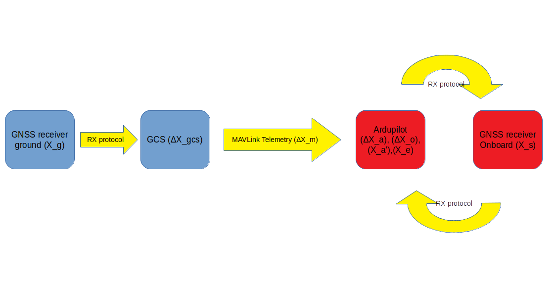
Information Path

  1. A GNSS receiver on the ground station records position solutions: X_g
  2. X_g is converted to RTCM correction data [2] and sent to a GCS, which records it as X_gcs [3]
  3. The GCS sends the solution to the UAV through the GPS_RTCM_DATA MAVLink message [4], containing X_m. The corrections are sent as a binary blob, possibly fragmented into up to 4 messages and sent across multiple messages.
  4. Ardupilot captures the MAVLink message and unpacks the RTCM packets into an ‘rtcm_buffer’ struct [5]. It stores the correction data struct ΔX_a until it is complete.
  5. Ardupilot sends ΔX_a to the onboard GNSS receiver [6], repackaging it as ΔX_o (the original form), according to the receiver driver [7].
  6. The onboard GNSS receiver calculates the correction, creating a more accurate solution X_s
  7. X_s is sent from the onboard receiver to Ardupilot, which stores it as X_a’
  8. Ardupilot uses X_a’ in its EKF [8], producing a final position solution X_e [9]

The following image visualizes this information path:

Quantity Representation and Precision

The following table summarizes the representation of each quantity and the precision it can achieve.
All quantities are in degrees when expressed in floats and degrees * 1e7 when expressed in integers.

Quantity Representation Representation Precision Actual Propagated Precision
X_g (Based on driver) (maximum) (maximum)
X_gcs (RTCM) (maximum) (maximum)
X_m MAVLink GPS_RTCM_DATA (maximum) (maximum)
ΔX_a uint8_t rtcm_buffer::buffer (maximum) (maximum)
ΔX_o (Based on driver) (maximum) (maximum)
X_s (Based on driver) (maximum) (maximum)
X_a’ int32 full (integer) (degrees, 7 digits at best)
X_e float32 7.2 digits [1] (meters, decimeter-level)

Specifics on EKF implementation

For this section, we shall examine EKF3, which is the latest EKF revision.

Every Kalman filter has

  • a measurement update step, where sensor data is made available and read
  • a model update step, where the internal model is propagated and
  • an output step, where the filtered data is made available

In this case, EKF3 reads from the GPS driver

const struct Location &gpsloc = gps.location();

where the GPS location is made available in WGS84 coordinates:

struct PACKED Location {
    union {
        Location_Option_Flags flags;                    ///< options bitmask (1<<0 = relative altitude)
        uint8_t options;                                /// allows writing all flags to eeprom as one byte
    };
    // by making alt 24 bit we can make p1 in a command 16 bit,
    // allowing an accurate angle in centi-degrees. This keeps the
    // storage cost per mission item at 15 bytes, and allows mission
    // altitudes of up to +/- 83km
    int32_t alt:24;                                     ///< param 2 - Altitude in centimeters (meters * 100) see LOCATION_ALT_MAX_M
    int32_t lat;                                        ///< param 3 - Latitude * 10**7
    int32_t lng;                                        ///< param 4 - Longitude * 10**7
};

The current coordinates are subtracted from the EKF origin to obtain the current XY offset:

gpsDataNew.pos = location_diff(EKF_origin, gpsloc);
gpsDataNew.hgt = (float)((double)0.01 * (double)gpsloc.alt - ekfGpsRefHgt);

which is a Float32 variable:

struct gps_elements {
    Vector2f    pos;            // horizontal North East position of the GPS antenna in local NED earth frame (m)
    float       hgt;            // height of the GPS antenna in local NED earth frame (m)
    Vector3f    vel;            // velocity of the GPS antenna in local NED earth frame (m/sec)
    uint32_t    time_ms;        // measurement timestamp (msec)
    uint8_t     sensor_idx;     // unique integer identifying the GPS sensor
};

These are used during the model update to propagate the vehicle state. This state is declared as:

struct state_elements {
    Quaternion  quat;           // quaternion defining rotation from local NED earth frame to body frame
    Vector3f    velocity;       // velocity of IMU in local NED earth frame (m/sec)
    Vector3f    position;       // position of IMU in local NED earth frame (m)
    Vector3f    gyro_bias;      // body frame delta angle IMU bias vector (rad)
    Vector3f    accel_bias;     // body frame delta velocity IMU bias vector (m/sec)
    Vector3f    earth_magfield; // earth frame magnetic field vector (Gauss)
    Vector3f    body_magfield;  // body frame magnetic field vector (Gauss)
    Vector2f    wind_vel;       // horizontal North East wind velocity vector in local NED earth frame (m/sec)
};

In turn, this state is manipulated to produce the filter output:

posNE.x = outputDataNew.position.x + posOffsetNED.x;
posNE.y = outputDataNew.position.y + posOffsetNED.y;

declared as:

struct output_elements {
    Quaternion  quat;           // quaternion defining rotation from local NED earth frame to body frame
    Vector3f    velocity;       // velocity of body frame origin in local NED earth frame (m/sec)
    Vector3f    position;       // position of body frame origin in local NED earth frame (m)
};

Remarks

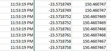
  1. EKF reads the GPS location in WGS84 coordinates which is already constrained in accuracy by its int32 representation at 11cm, truncating potential RTK precision. I don’t know if the otherwise superior position accuracy is correctly downgraded to reflect this truncation.
  2. The position measurement is stored as a relative coordinate in meters (float32) , converting from WGS84 coordinates to the NED Cartesian frame.
  3. The filtered position is returned in the NED frame in meters (float32).

Assumptions

  1. Correction data is transmitted through MAVLInk and the telemetry channel, not via a dedicated RF channel.

Conclusions

  1. The autopilot internal location representation is a bottleneck for the RTK solution precision, limiting it to 7 digits (about 11mm)
  2. It looks like the precision could me immediately improved by creating a more accurate GPS driver. The EKF is otherwise ready to accept the improved precision.

Further Questions

Is everything clear? Do you need better wording someplace?


Footnotes

[1] See https://www.h-schmidt.net/FloatConverter/IEEE754.html for actual error calculations.
[2] https://gssc.esa.int/navipedia/index.php/DGNSS_Standards
[3] https://github.com/ArduPilot/MAVProxy/blob/ec5cd22e22469d1107c0259bb71508fb99293e14/MAVProxy/modules/mavproxy_DGPS.py#L58
[4] https://mavlink.io/en/messages/common.html#GPS_RTCM_DATA
[5] https://github.com/ArduPilot/ardupilot/blob/90216f7cb6c5fd20cc5020b935a7985b1a549949/libraries/AP_GPS/AP_GPS.h#L505
[6] https://github.com/ArduPilot/ardupilot/blob/922d593f3d28cdd0959178ec2ae3cc41ce040ad0/libraries/AP_GPS/AP_GPS.cpp#L865
[7] https://github.com/ArduPilot/ardupilot/blob/1b6ec1d5ad33567e0bc62a2a1f6a5bb2b68fe31b/libraries/AP_GPS/GPS_Backend.cpp
[8] https://github.com/ArduPilot/ardupilot/blob/1b6ec1d5ad33567e0bc62a2a1f6a5bb2b68fe31b/libraries/AP_NavEKF3/AP_NavEKF3_Measurements.cpp#L565
[9] https://github.com/ArduPilot/ardupilot/blob/1b6ec1d5ad33567e0bc62a2a1f6a5bb2b68fe31b/libraries/AP_NavEKF3/AP_NavEKF3_Outputs.cpp#L239


Edits

  • 2018/11/23: Incorporated RTCM data into the information flow.
  • 2018/11/25: Updated information flow image, ArduPilot RTCM handling
  • 2019/01/08: Traced the EKF3 internals
2 Likes

There are a couple of reductions in precision that you listed that aren’t correct. RTK corrections are almost universially managed with RTCM, and even when they aren’t there is not a MAVLink encoding of the correction data. Instead it’s just a way to transport arbitrary blobs and inject them into the autopilot then the GCS. There is no loss of precisision anywhere between the ground correction source and the aircraft GPS output. That means that propregated precision would be maximum all the way through X_s. From there the precision varies depending upon the specific GPS driver you are using, but in general all the GPS drivers actually have 7 decimal places of precision. (Either the location is actually sent as an integer of location * 1e7 and done on the GPS, or it’s sent as a double (float64), and we extract it into an integer * 1e7 via double math)

This is also purely a precision discussion, which ignores other errors which will be on the same scale to significantly larger (correction latency, base station location accuracy, baseline length, timing and sensor accuracy on other inputs to the EKF).

TL;DR
MAVLink packet for sending corrections is not a bottleneck, although it does represent an precision limit if you are attempting to extract output coordinates from the aircraft via MAVLink.

1 Like

Thank you for your reply,

I’ll hunt into the code the variable declarations for documentation purposes and edit my post for completeness.

Editing the drivers to use double instead of floats doesn’t sound do gnarly. Double math is much slower than float, but sparse use won’t break the loop rate.

On the other hand, converting the EKF to double could have a significant impact on memory and loop rate.

Is any of the above the reason why this hasn’t been done yet, or it’s just that demand isn’t high enough?


Regarding precision loss, it’s true that hunting down all of the error sources and propagating them down to the EKF is an ugly business. That’s why one would pay $$$$$ for a good INS and still have have to be careful with the integration.

Hunted down some sources for RTCM correction representation. Inserted links where appropriate.
Will follow up with more info on the UAV side.

Updated flow diagram and fixed information up to on-board GNSS receiver.

Thank you @Georacer for inputting some useful information on this.
While RTK still seems to be the rising ‘catch phrase’ it would be good to get this precision shortcoming sorted.

I feel it would be of great benefit in the long run to Ardupilot to have this extra precision added.
Your work has at least narrowed down where we should be looking for improvements.

You’re welcome! I’m not done yet, although I am sure @WickedShell has already answered the question on which are the pain points.

Still, I hope that if I do a good enough job in documentation, it may become easier to someone to make some progress on the matter.

X_a' and X_e are both stored in int32’s and have exactly 7 decimal places of precision.