So first up I may have posted this in the wrong place. I am just not sure where the question should be asked.
So here is the question.
In checking the log on a rebuild of a machine I crashed. One of the things I have been paying attention to is VCC. I want to make sure that the FC is getting the power it needs. According to everything I have read and all the power modules I have ever had. 5.3 volts is the magic number. So I am taking great pains to make sure the fc is getting what it needs.
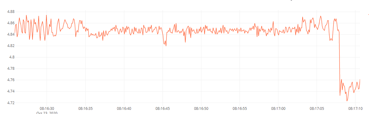
So today I pull the log after doing the first armed test and one thing I check is vcc. Much to my surprise. This is what I see
Now I checked the input voltage and found it was actually 5.1 volts and bouncing when the GPS is attached…I suspect thats due to it having an I2C external LED on it so as it flashes it’s causing some voltage fluctuations.
If I unplug the GPS the voltage remains steady at 5.1…so I know I need to tweak it to 5.3…that I can fix.
I should note that the gps and fc are on the same bec…but the gps is not powered through the fc. I needed to ensure the GPS and the FC had redundant power but not power it through the fc.
So what I don’t understand is why do I see a VCC with a mean average of 4.84…if 5.1 is going in.???
Is the voltage measurement in someway firmware controlled…I am puzzled by this.
Well, the original design feed the VCC to an analog input of the processor, via a voltage divider. In the case of Cube these resistors has 0.1% precision and the measurements are ok.
If the resistors in the divider are not 0.1% (which is very likely in the case of PixRacer) then it is very likely that readings are off.
Hey Andras. I was suspecting something like that.
I wonder how one would go and find out. I do need to tweak the input voltage to ensure it’s 5.3 volts…but now starting to think I am chasing ghosts.
Just use a multimeter to measure and adjust accordingly your power source. If you are not using analog sensors (like an airspeed) then you will be ok with a slightly off onboard measurement.
The processor has it’s own power monitoring so it will not be impacted it.
I have noticed this before and ignored it. BTW-One of these is an origanal CUAV (before Mro) the other 2 are clones. I don’t know which is which w/o taking them out of case.
Hey Dave.
Do you know if these are reporting different then what you can measure as the input voltage.
I can see the variance between units, but is it possible the input voltage is different or are they all 5.3v.
I may start ignoring it but want to make sure. To many years in operations I just can’t yet say ignore it.
Not so easy to measure now. 2 of them have the cheap Power Module, which usually do provide 5.3V (or thereabout) and the other is an overpriced ACSP4 from Mro.
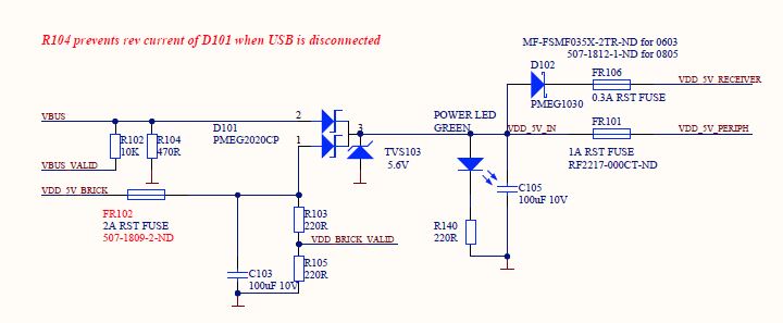
If you are interested this is an old Rev but maybe not changed:
I don’t think It’s a resistor issue. let’s say you used a voltage divider with 220ohm 1% precision resistor
220 * 101% = 222.2
5 / (222.2*2) * 220 * 2 = 4.95V
the result will be 5V ±0.05, and the processor only have 12bit ADC, you don’t really need the 0.1% precision resistor, my guess is the power is must go through some diode or mosfet, loss some voltage on those components and the process is mesured the voltage after those components and get the lower voltage than the input, you should mesure CAN, I2C, serialx’s VCC as a reference, see the result is the same from the input, if so you can raise the BEC’s output a little bit.
Hey thanks for that input very interesting.
I will take your suggestion and measure the power on the Can port or the GPS port as they are both powered from the same bec. all other devices are on separate power so that would be pointless.
I can then tweak the output if it’s needed.
According to the schematics 5Vin goes through only one diode which have a maximum 300mV forward voltage, then it goes directly to the voltage divider (2x 10K) and to the analog input of the processor. So voltage drop does not explain the 4.8V measured voltage.
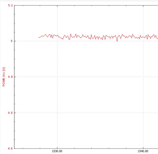
Although measuring at gps or can is a good way to see what is the voltage on the 5V rail.
Thanks Andras
First chance I get I will test the GPS 5v rail. My guess is I am going to see about 5.1v but will check and report back. My gut is telling me the pixracer is reporting low but will do the work first.
So on the Pixracer I can see the input voltage is 5.1 and the pixracer reports 4.84.
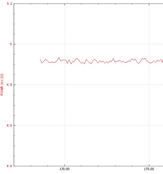
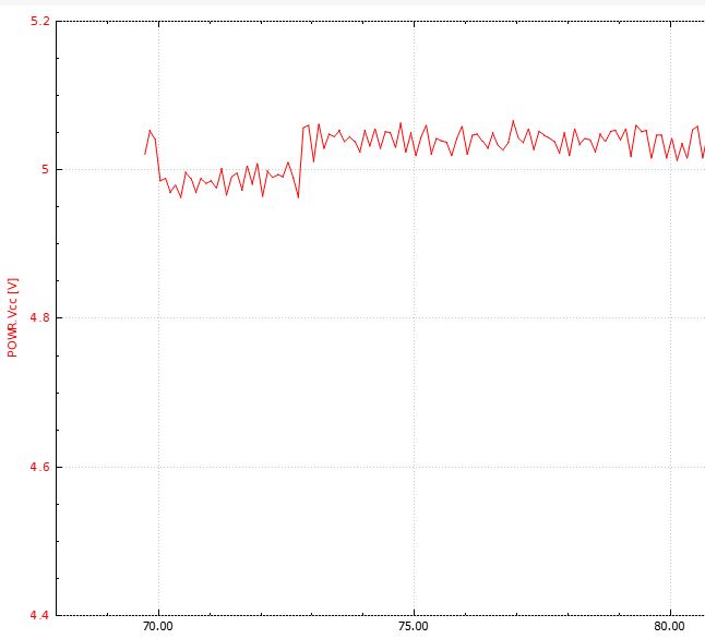
On my Pixhawk 2.4.6 The input voltage is 5.3 but when the pixhawk is connected it drags the voltage down to 4.9vdc. Interesting,
With the Pixracer I would say Nothing To See Here. I have had the 3 I have on multiple craft, multirotors and Rovers, with different power options. All good regardless of what’s reported as Vcc.
Hey guys any idea at what voltage a brownout would occur on both the pixracer and Pixhawk. I am just wanting to keep an eye on voltages as I don’t want any more crashes.
Driving too many loads off of the power module. I power the GPS, telemetry radio, flight controller and the RC receiver off of the power module and that’s it. Never had a brown out.
I use separate +5 and +12 volt BECs to power landing gear, external navigation LEDs, OSDs, FPV Tx and camera, GoPros and gimbals.
Hey @OldGazer
I like you power stuff separately. But what I am trying to figure out is at what point the flight controller would go off line do to low voltage.
Just looking to ensure I take low voltage into account for reduncancy.