Hi all,
I have spent some time now working to set up copter on my 250 race quad. It has left me scratching my head for a while but I have finally got things working. So I wanted to take this opportunity to share what I have learnt so far and I hope others will be able kind enough to correct me where I have made mistakes so that I can learn more.
Setup:
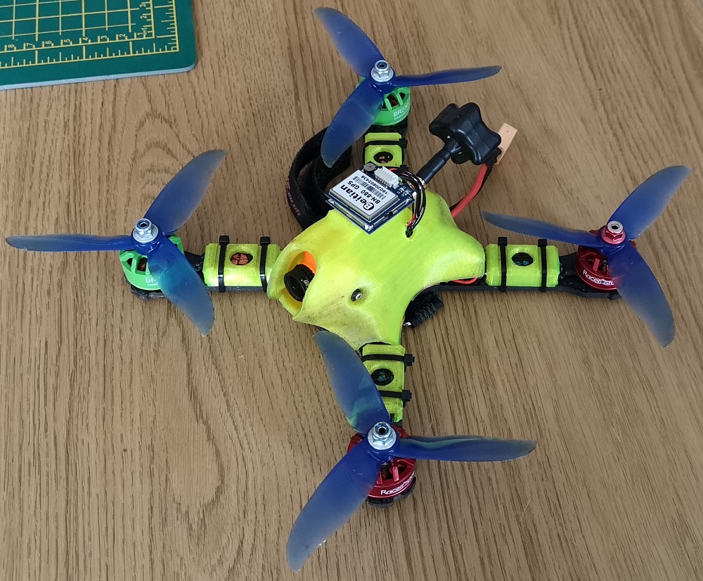
FC: Omnibus F4 V5 (not the pro version) running a daily build of 3.6.0 from 3rd Aug 2018
Reciever: FrSky XM+ micro receiver using SBUS
PDB: Mateksys HUBOSD8-SE
FPV: RunCam Sparrow camera, RC Immersion Tramp VTX, using onboard (onboard the omnibus that is) OSD.
GPS: Beitian BN-880 GPS
I used the instructions on the wiki to flash the boot loader and copter onto the board. I have had limited success with this method. It only worked about 1 in 5 times. I have found that flashing the firmware via beta flight (as described here) works every time. I originally flashed 3.6.0-rc7 and it worked fine including writing logs to the sd card. The only trouble is that the on-board OSD wouldn’t work. I subsequently found that the daily build from 3rd Aug 2018 works well, with both osd and data flash logs working!
Please not that on the Omnibus F4 setup guide on the wiki it talks about jumping solder pads or removing resistors to select between SBUS and PPM receiver protocols. This is certainly true for the V2 and V3 F4 boards. It is not required for the V5 board. Simply solder your receiver to J7, on the attached pinout, and arducopter will automatically detect which protocol your receiver is using. Very neat!
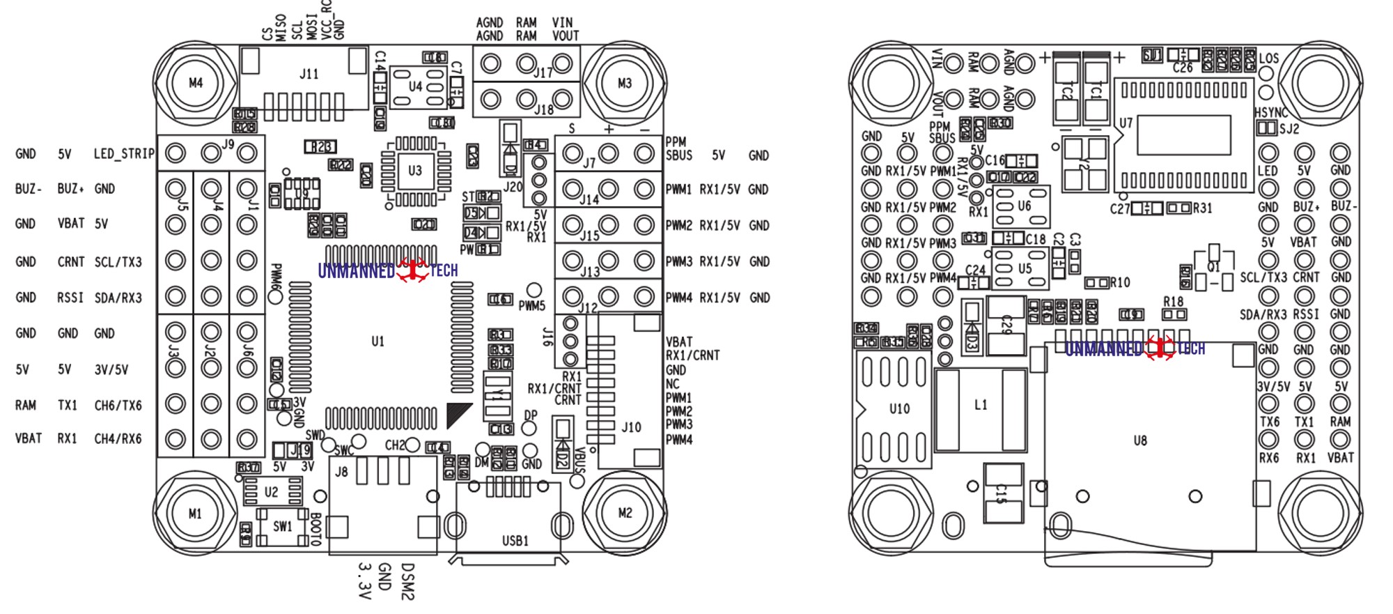
As this isn’t the pro version of the board it doesn’t have a current sensor. There is however a current sensor on the PDB. I connected the ‘GND’ and ‘Curr’ outputs from the PDB to the ‘GND’ and ‘CRNT’ pins on J5 and J4 respectively. I am also powering the board with battery voltage via the ‘VBAT’ pin on J4. This gives me battery voltage and current on my OSD which I have found very useful. Having now calibrated the voltage and current inputs in mission planner I am pleased to report that it is working reliably.
I am powering both my VTX and camera off of the 10V outputs on the PDB. The Video out from the camera is connected to ‘VIN’ on J17 and the video output is connected to the ‘VOUT’ on J18. I have also run a common ground from ‘AGND’ on J17 to the same ground on my PDB. I have copied this setup from the excellent blog on dronetest (here) under the section entitled ‘Connecting your FPV Gear’. What I have done slightly differently is I have run the audio output from the camera straight to the audio input on the VTX. This setup works well for using the on board OSD function that ardupilot now offers. I must say that the OSD in arducopter is fantastic. Highly customisable and loads of options for telemetry that you may or may not want to display. Thank you to the devs that have put this together!
GPS. Ahhhh the GPS. This one has plagued me for quite a while but I am pleased to say that I now have it working. Originally I was trying to connect an OP GPS with a UBLOX 7 chip that I got from Amazon. I tried everything to get it to work. I connected to Rx6/Tx6, I connected it to Rx1/Tx1. I made sure that I was connecting Rx->Tx and Tx->Rx. I even swapped the Rx and Tx pins on the GPS just in case the pin outs were incorrect. I switched on all of the serial ports (1 to 6) to be gps. I had another identical gps that I tired. But nothing! bupkiss! Mission planner always displayed ‘GPS: No GPS’. I combed the internet to try and find out what was going wrong. I finally stumbled across an article the mentioned that this gps is optimised for open pilot. So i tried a different gps that I had, the Beitian BN-880 GPS, and it worked first time! The relief!!! The GPS is now connected on Rx1/Tx1 which corresponds to UART1. In mission planner the serial port protocol is controlled via the parameter ‘SERIAL1_PROTOCOL’. Note that if you want to use either UART3 or UART6 for your GPS it will require you to do a little edit in the code and build the code yourself. Rx3/Tx3 on J4 are currently hard coded as an I2C port. To change this you will need to change those two pins to be UART pins. Rx6/Tx6 (for UART6) have been inverted and you will therefore have to change the pins to output high if you are using a gps on those outputs. This can all be done in path:\libraries\AP_HAL_ChibiOS\hwdef\omnibusf4pro\hwdef.dat. I have decided not to use the compass that is fitted to the BN-880 as I fear there will simply be too much EM interference on my race quad. I know that @iampete has been having issues with the compass on his race quad. So I hope to find a smaller GPS unit than the BN-880 to make my build a bit tidier.
My question to you all: Is there something I should be aware of when looking to get a GPS that will work with arducopter? I think that the reason the OP GPS with a UBLOX 7 chip doesn’t work is because of how the UART back end handles the buffering of the data (i.e. it doesn’t). Any advice here would be greatly received! 
Maiden and tuning: With my race quad being incredibly powerful the default rate PID did not work at all. This is precisely as @fnoop described in this thread. The P,I, and D values are tiny in comparison to the defaults. In fact they are lower than mission planner’s suggested range. To give you a feel for it, to get my quad flying i initially set all rate I and D values to zero and managed to get it flying with rate P values of 0.022 for pitch and roll. I have since been trying to use auto tune to improve the tune, with limited success so far. I am going to continue with trying to get the auto tune to work for now but I may have to resort to doing it the old fashion way to get a really tight tune.
Anyway, I hope that this information will provide useful to someone, who like me, has been banging their head against the wall trying to get this board to work. I will post updates and videos as I continue to make progress with this build.