I am a bit confused with 8-Pin for the Motor/Servo that goes directly to 4in1 ESC such as the Ori32.
Since I’m not going to be using the 4in1 ESC, I was wondering is it possible to solder the servo signal (white cable) directly to one of the end of the 8-pin connector cable, while the ZOHD servos and motors will be powered through the 5V_BEC and Ground Pad on the the Omnibus F4 Nano Flight Controller?
Based on the reference: https://ardupilot.org/copter/docs/common-omnibusnanov6.html, the 8-Pin from the FC is capable of both PWM and DShot. The problem is, I’m not quite if the FC will automatically detect a PWM or DShot signal, unless configuration is needed in the Mission Planner parameters.
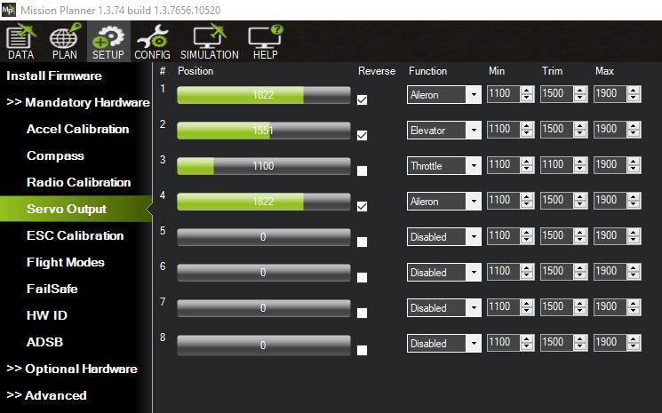
Either way, I decided to solder the M1, M2, M3 cables to the servo connector, with the red (positive) cable going to the 5V_BEC pad on the FC, and the black (negative) cable to the GND pad. So far, it’s working, but the only problem is the mapping is all mixed up. The diagram was kind of confusing, since I’m not quite sure which Servo mapping its referring to, since it just mention “Motor/Servo 0” for the first four pins.
It seems I was able to figure out the aileron, and elevator, but the motor mapping is referring to as “Rudder” except “Throttle”. I tried playing around with the RCMAP parameter, but its still recognizing itself as a rudder, instead of throttle. From the R/C Transmitter, I am still able to control the motor using the throttle stick, but the mapping in the Mission Planner might cause problem when it’s flying on autopilot.
Another thing I notice is when I turned off the transmitter, the motor would start spinning without any inputs.
Awsome, thank you very much Dave! I very much appreciate it. That really saved me a lot of time trying to figure out the configuration.
Regarding the ESC BEC. How are you powering multiple servos to the ESC BEC? The ZOHD ESC has the servo connector for the motor, and the VTX power connector. Did you splice the power cables, or have the VTX powered from the FC, and used that connector to power the servos?
Just uploaded the parameters, and it seems that didn’t work, unless I did something wrong here. I went to the Full Parameter List, load the parameters from files, and its showing that its missing 94 parameters. Just to make sure, is your F4 Nano v6 or v6.1? I think I should have clarified that.
Ah sorry, should have warned you. Never load someone else’s parameter file.I don’t even do that with my own back-up copies. Review it and make changes manually if you want. The reason for the missing parameters is this is a dev version of firmware. You will have to reset to default and start over. Only use the parameter file for a general guideline. I find the best way to use it is with Paramter Compare in Mission Planner or Text File compare utility.
For the ESC BEC I just took the 5v out lead and commonly connected them to all the servos. I used the VTx lead to power the FC.
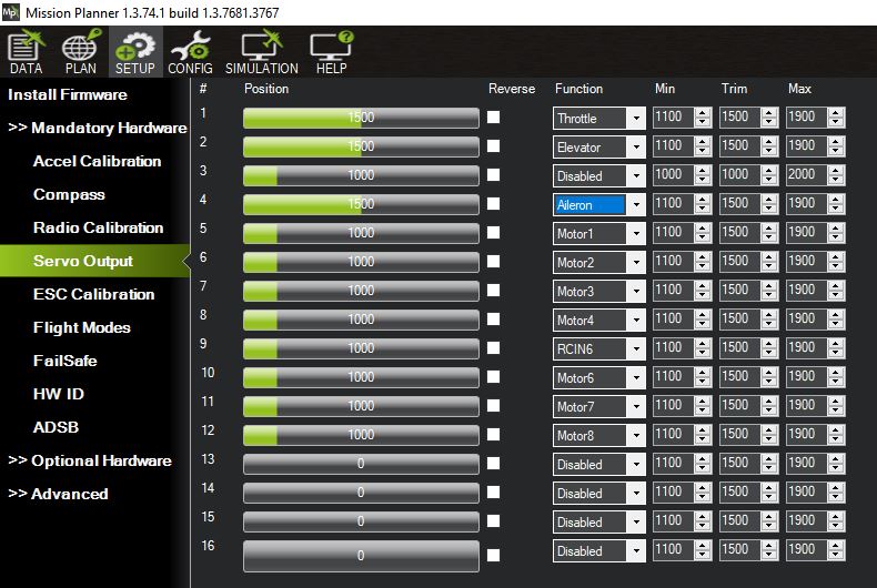
So you have throttle signal on Servo 1 (M1) , Elevator on Servo2 (M2) and both Ailerons Y together (why do that?) on Servo 4 (M4). Obviously my setup is different so my parameter file won’t work for your setup. I figured you would look at my parameter file and how the servo outputs were assigned and use that info to suite your setup.
You can use a Y-splitter for the Ailerons and control them with one output but for maximum flexibility you might want independent control. In actuality this doesn’t have much use with the Drift but in general it’s best practice to do it. For flaperons for example. But as I say you could just leave it as is if you like.
Okay, it was something very simple that I overlooked. It was disarmed… It seems like everything is working so far. I’m going to do some more test to be sure. Thanks again, Dave!