Motor Test is actuating the wrong ESC pins

Holybro Pixhawk 4, 1 week old
Copter 4.0.7 OFFICIAL
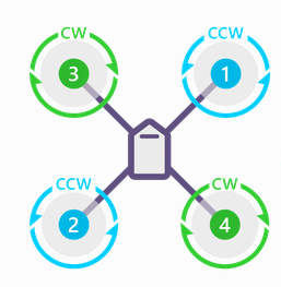
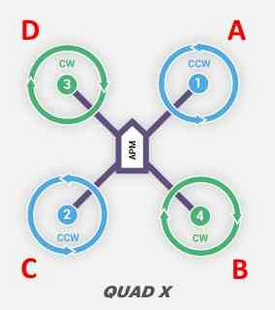
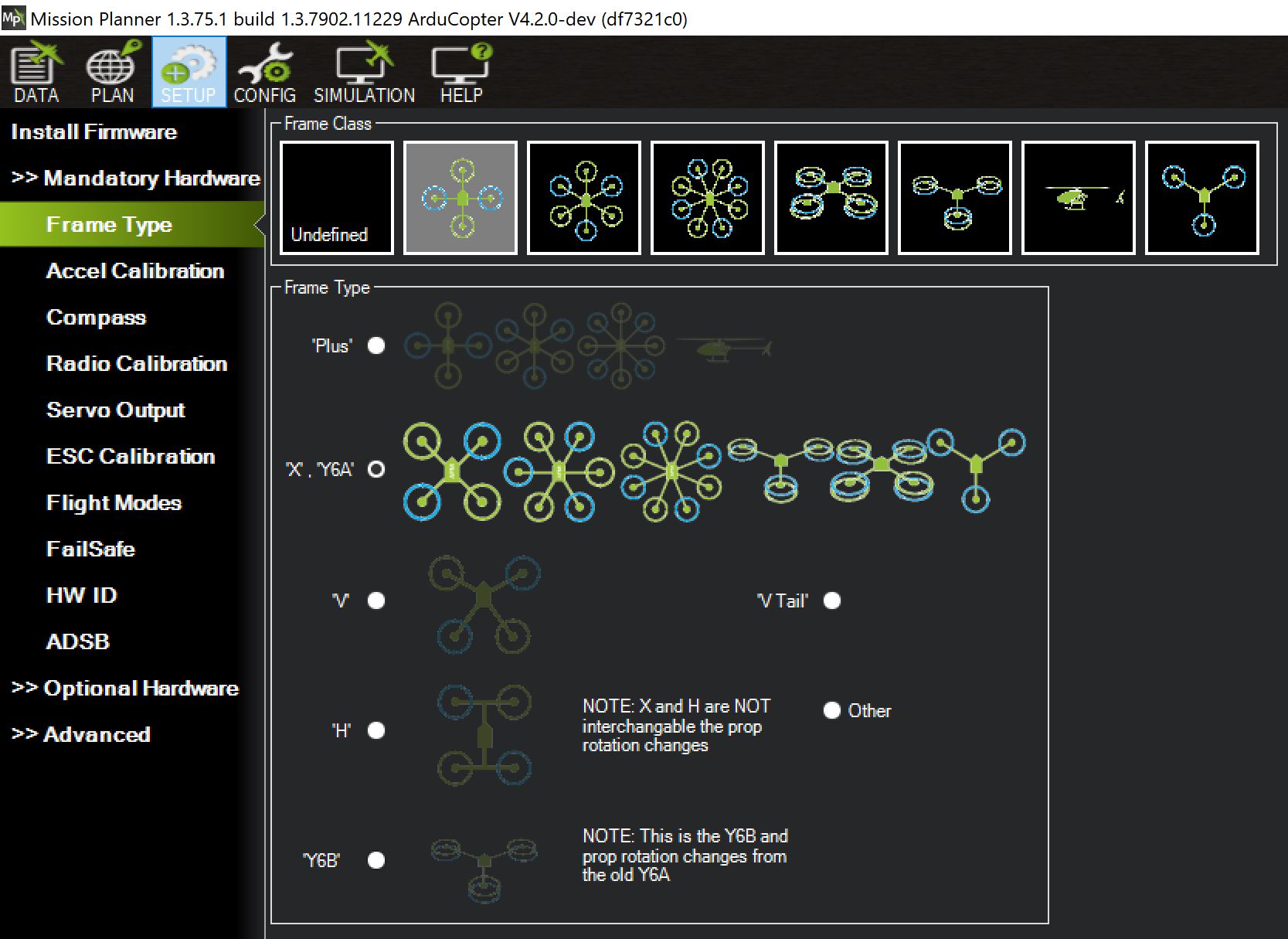
Frame Type: “X”
ESC Type: Normal
ESCs 1 to 4 connected to Pixhawk4 IO PWM OUT, pins 1 TO 4, respectively
I buzzed these out to ensure proper wiring
Servo Outputs 1 to 4 connected to Motor Functions 1 to 4, respectively
Servo Outputs 5 to 8 all Disabled

When I first did the Motor Test “Test all motors”, all motors started up and ran properly in the correct direction. When I ran “Test all in sequence”, the motors ran out of sequence, with large time gaps between motors.

Using an O’scope, I ldid some troubleshooting and found the following:
Using Motor Test to test each motor individually, I found:
a. Test Motor “A” drove pin 1 (correct)
b. Test Motor “B” drove pin 6 (incorrect)
c. Test Motor “C” drove pin 4 (incorrect)
d. Test Motor “D” drove pin 7 (incorrect)

I then went to Servo Outputs and connected, one by one, in turn, Servo Outputs 1 to 4 to
RCIN3 (throttle). When I advanced the transmitter throttle, motors 1 to 4 ran
properly, as determined by the current Servo Output.

My most important question is "Based upon the above, is it safe to fly the copter?’

Note that I just finished building a hexcopter and a quadcopter, running 4.0.7, each on a
plain vanilla Pixhawk and everything is perfect. The current build uses a Pixhawk4, and
that is the one having the Motor Test problem.

Post the parameter file.

The motor order NUMBERs are not the same as the MissionPlanner motor order LETTERs
Wire it all up as per the arducopter docs with “Servo Outputs 1 to 4 connected to Motor Functions 1 to 4, respectively” as you had it.
And you should have these parameters
SERVO1_FUNCTION,33
SERVO2_FUNCTION,34
SERVO3_FUNCTION,35
SERVO4_FUNCTION,36

image

When you try the MP motor test,
Test Motor “A” will spin the front right motor (1)
Test Motor “B” will spin the back right motor (4)
Test Motor “C” will spin the back left motor (2)
Test Motor “D” will spin the front left motor (3)

So you can see the MP motor test activates each motor in turn clockwise around the motors.

image

First let me thank you for the prompt answer. Your answer is extremely clear, and is what I EXPECTED to happen. Remember, this is the third copter that I have built within the last 6 months and the previous two, both of which used a Pixhawk 1, did exactly as you described.

I am having the problem ONLY with my current build which is using a Holybro Pixhawk 4. I have ESCs 1 to 4 (Using Standard protocol) plugged into IO PHYSICAL pins 1 to 4, respectively, but I do not get the expected results. For instance, I would expect both “SERVO2_FUNCTION, 34” and “Test Motor C”, to both actuate the rear left motor, i.e. the motor shown as #2, but this is not what is happening. In order to get Motor Test to run motor (2), I have click on “Test motor G”. I know this sounds crazy, but this is what is happening. I could, for example, see this happening if the SERVO_FUNCTIONs, and Motor Test, do not use the same motor number to physical pin number mapping table, and there is an error in the Motor Test table.

Using Motor Test, I actuated each Motor Letter in turn and inspected ALL output pins with an oscilloscope. Here is what I found: Motor A drives Physical Pin #1; B drives 6, C drives 4, D drives 7, E drives 5, F drives 8, G drives 2 and; H drives 5

Also, as I originally described
“I then went to Servo Outputs and connected one by one, in turn, Servo Outputs 1 to 4 to
RCIN3 (throttle). When I advanced the transmitter throttle, motors 1 to 4 (in turn) ran
properly, as determined by the current Servo Output that is connected to RCIN3.”

When I saw this, I didn’t believe it, so I have spent 3 days trying to find my mistake, including setting parameters to defaults and reloading the firmware. Neither solved the problem. So, any ideas??? If I ignore the Motor Test, and I know that the SERVO(1 to 4)_FUNCTION drives motors (1 to 4), do you think that it is it safe to fly?

I used WeTransfer. The link to the parm file is:

Then you know the difference between a Quad and an OctoQuad. You have FRAME_CLASS set to 4.

A fairly common mistake.

THANK YOU!!! I would NEVER have found this. I changed frame class to 1 and it now works perfectly. However, I will say that the selection was not obvious to me in the “Frame Type” graphic, since I went by the “X” shape, and not the motor count. I also searched the web and could not find anything that pointed me to this problem, so some kind of note on the graphic would surely help future users. Anyway, your help is very much appreciated.

You’re welcome Bob. This has been reported several times before for that same reason so it was kind of low hanging fruit if you have been around the forum. A couple clues can also solve this. Looking at the Servo Output screen and wondering why 8 motors are configured. Or, and it’s good practice anyway, review the channel assignments in the full parameter list.

BTW-Your test of Motor outputs and seeing outputs on 6&7 was good but not definitive because you can assign multiple outputs to the same motor. This is usually done by mistake and the FC will do it.

Yes, the tell-tale sign is MissionPlanner motor test provides the correct number of motor test buttons for your configuration - so if you are working on a quad and you’ve got 6 or 8 motor test buttons (anything other than 4) then the frame config is wrong.

I noticed extra motors, but did not understand the significance. Anyway, as a suggestion, you might consider adding the following type of comment:
Frame Class row: Select the graphic with the proper number of arms and motor count. Frame orientation does not matter. For a standard quad, this would be the first picture
.
Frame Type row: Select the orientation that matches your vehicle. For a standard “X” frame this would be row 2. For a “Plus” frame this would be row 1

Like this?

I don’t any attention to those icons. I load a type (Plane, Copter, Rover) and then set the right type and class in the full parameter list.

I agree that the parameter list is a great way to go, but you have to be quite familiar with MP to do that. I do not think that a beginner would be able to use parameters. Also, when you said “Like this”, isn’t the attached picture the same as the current MP? In any event, I am not trying to waste your time in an endless message exchange, I am just trying to help make MP a little easier for those who are less knowledgeable.

Yes, current, and for quite some time, Mission Planner config. If a new user steps thru the Mandatory Hardware, where Frame Type is the 1st selection, and ends at Failsafe, then they are at a pre-flight condition. I think this is detailed in the Wiki actually. So the biggest issue I see is not following the documented process

To get a sense of the test motor pattern vs. the propeller pattern, look at the code here:

the add motor method is define as