Nice designs and 3d prints ronsard!
I’d like to add a link to them if I may from the Mozzie docs?
The reason why the avionics was further rear is because of the vial holder which needed to be on the CoG, as in the competition the person could not change the CoG after placing it. For non competition aircraft that isnt required. I also like your damping system better than ours!
(EDIT P.S. How do you install and remove the avionics package after the fuselage is assembled with the custom 3D printed wing box? Ours was mounted with two screws through the fuselage so it could be easily and quickly replaced.)
I’m not intentionally trying to be vague, but rather just trying to explain of the dynamics of quadplanes and how they differ from conventional plane configurations. I agree that you need to “start somewhere” and there’s two ways to do this:
you get the FX61 airborne by whatever propulsion means and determine Carson’s by completing some zero propulsion descent rate tests. One way is to power down from high speed flight and maintain exact altitude until stall, say using alt hold. (which BTW is not always recommended with wings that can go into a unrecoverable flat spin even from 3-4 mistakes high). Ideally the quadplane setup would already be installed for this to aid recovery, and give realistic drag.
you install a motor with significant power, so more than required for cruise, and go through a series of tests to determine the best endurance/range for each prop.
Note that even a 30g 2206 sized motor can produce over 2kg of thrust now a days, so there is no real benefit in having a undersized, lightweight motor that only does a specific thrust to weight ratio to save a few grams. The thrust to weight ratio also doesn’t take into consideration at what airspeed the thrust is achieved. Hence why all high speed aircraft have variable pitch props. If your aircraft doesn’t have the right amount of thrust at the desired cruise airspeed, you’re essentially stuck in the “wrong gear”. In comparison the Mozzie drivetrain has better than 1:1, but only once the prop is at enough airspeed where it has enough “traction” and doesn’t stall. The efficiency defining factor with electric propulsion is the correct prop, that in hobby products are sometimes only 10% efficient at converting motor torque into thrust. This is where most gains can be achieved.
One place to start is to copy some other models like this one with 100km range:
According to the current draw data there the drivetrain power requirements are similar to the MT/Mozzie and he uses an even steeper pitch prop to achieve it with roughly the same MTOW. So the same motor prop from the Mozzie should be within the ballpark. Also note that even if the prop efficiency was high and around 10g/W that FX 61 is achieving that range with only around 400g of thrust at cruise, so 0.25. It’s likely you’ll need similar for a QP setup plus 10-20% more depending on how streamlined and small the QP setup is.
Thanks Sam I fully understand your requirements for a CG located payload bay for the Outback challenge.
The damping is inspired by the Omniarc one, and I have used it successfully in several large hexacopters.
In my design the complete avionics package can be removed in two different ways (or combinations of both).
The “uprights” for the lower damping balls can quickly be unscrewed with one screw each accessed from the front and rear compartments (black screw seen in the pictures). Then you can pull the complete assembly out through the center bay.
It can also be undone by sliding out the dowtalils for the front and rear frame center spars. These are secured with two screws each (silver ones in the pictures). These screws might also be omitted as the fit is quite tight.
No problem with the STL files. I will make them available when I see that everything fits nice Sam if you are interested, I should be able to share the cad files (fusion 360) as it makes refinement easier.
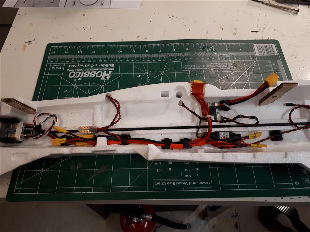
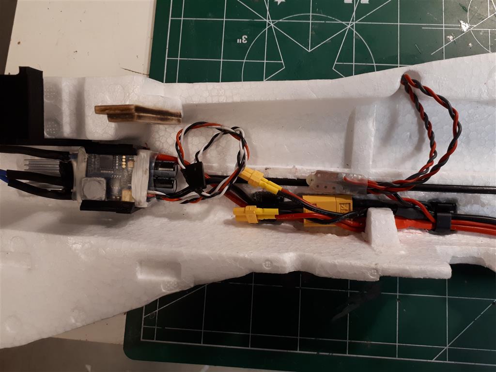
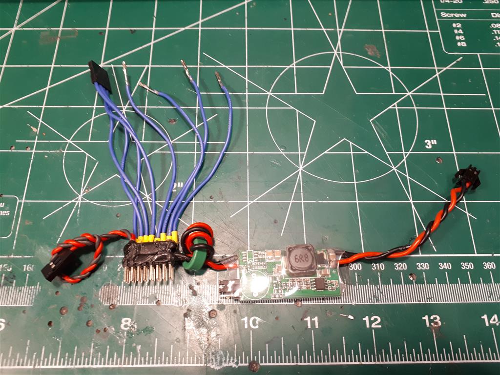
The power loom looks nice! I can see XT60s but what are those little yellow connectors? Are you using a Mauch Power Module? I wouldn’t recommend a 3DR PM on this project.
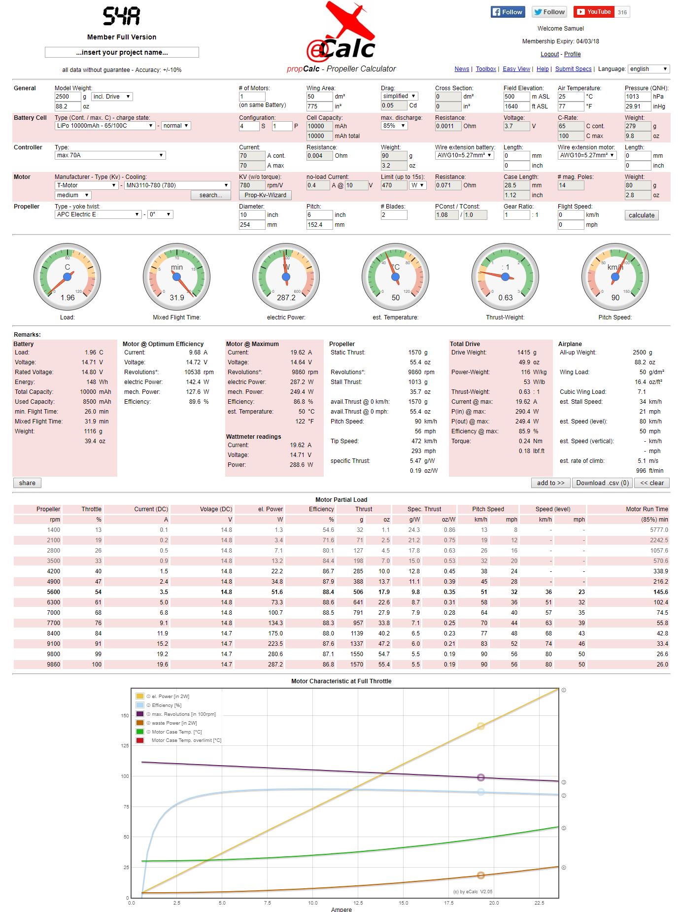
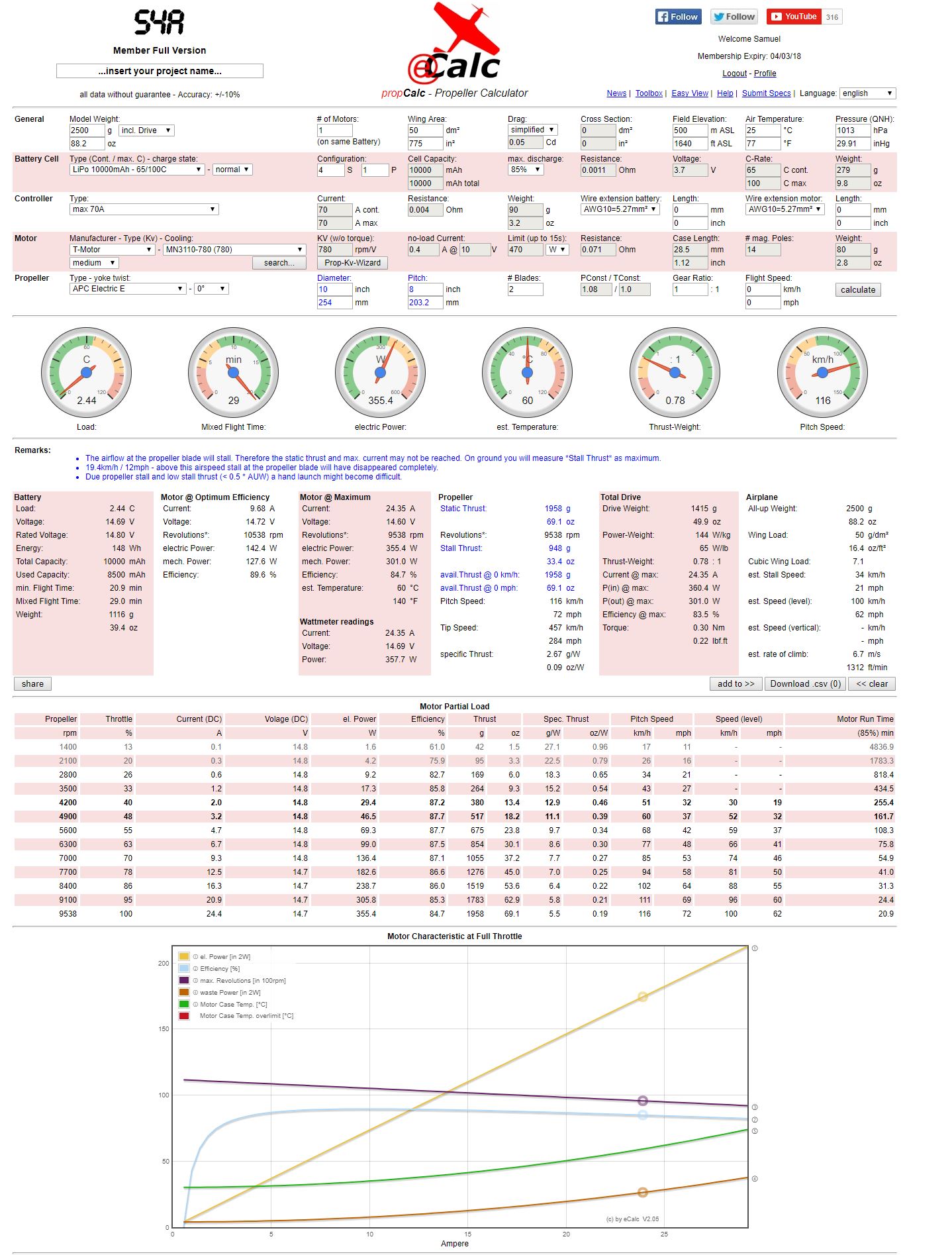
I don’t have much experience choosing engines, but have been really happy with t-motor U5s on my quad. So I plan to stick with t-motor for now. I plan to use the MN3110 with an APC 10X 6 prop. That gives me about .5 thrust to weight at 3k. I am hoping to come in a bit under that perhaps 2.9kg.
I’ll keep you appraised of my progress. Ordering from Banggood, which I’ve never done, is slowing me down. And my house is blowing up with boxes from Amazon.
Dave: I bought this motors for my F61 Sunnysky X2216-7 1400KV as Iskees recommend, they look good but now I’m waiting new esc for some unsync issues with the old ones that I installed at first. any change is a month to wait here but they are arriving soon
Thanks for your kind word Sam. I have done quite a bit of soldering over the years, both in work and hobby. In any case I had forgotten the ubec for the Mauch PM in the above pictures I also added a small pdb in the rear for power to the PI and other equipment. The loom is, as yours, wired such that without the safety connector inserted there is only power to the FC, PI and aux equipment (no power to the ESCs and motors.
For the fire extinguisher; I have not had any accidents yet, but better safe than sorry
I ran that combination through ecalc, and that should be fine. The 10x6 will likely not have enough pitch and make to much thrust, if you look at the table at throttle 84% and then across, you’ll see that your making 1139g of thrust at 68kmh airspeed. (77kmh pitch speed) That’s about 2-3x as much thrust as I’d expect you to need to have at that speed with cruise around 68kmh. That 100km long range FX was only using around 350-400g of thrust, but at around 50kmh.
So a 10x6 will fly, and also takeoff and climb well, but it won’t be very efficient at cruise. A 10x8 will be better on a quadplane setup to optimise cruise, if not maybe even more, or otherwise you might have to go down to a 9" diameter. You’ll notice on the 10x8 it gives some warning’s regarding stalling prop on the ground, but because of the QP we don’t need to worry about it, as explained previously.
By the way ecalc is a good way to get your bearings around motors and props
How are you guys powering and connecting the servos, and what would be the preferable method these days?
connecting them directly to the output rail and powering the rail with a bec (+ Zener diode)
powering them from a bec and connecting the signals to the pixhawk. Are you then also connecting the servo ground wire to the pixhawk
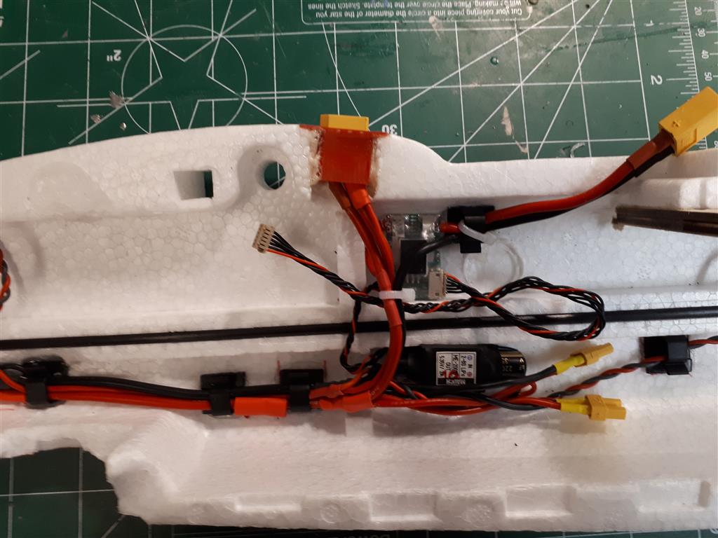
Below is and below is a bec with a powered rail for servos (the blue wires are the signals. The power cable on the left is NOT to be connected to the pixhawk). A separate bec is then thought to power the output rail. A Zener diode is again connected to to condition the power.
If you’re using a Pixhawk, simply connect the servos to the Pixhawk outputs and feed a separate 5v BEC into an unused output or aux port. Don’t connect the BEC to the RC or SBUS pins that have the 5.3v Power Module supply on them. The separate 5v BEC then acts as a redundant supply for your Pixhawk and will throw an alarm if the Power Module goes bad or is unplugged (for testing).
Yes I guess that is a good enough solution on a small plane like the MT On larger ones with more powerful servos I have usually powered the servos directly.
In general one should always have the servo ground connected on all PWM outputs, it’s also good practice to avoid adding connectors as potential failure points and having different lengths, or poorly routed ground and PWM signal cables. For the MT directly using the PXH is more than adequate.
I see you have the twisted cables sorted already, so that’s something I can’t add.
Sam, it is not completely clear to me from the Mozzie instructions, but I assume you are using one BEC for the servos (connected to the aux output rail on PH) and one BEC for the PI (also powering the PH through usb).
It looks like these are placed outside the avionics box. Is this correct?
Any reason for not putting them inside the if there is space (heat, RF noise etc)
We put the UBECs externally mostly because for the competition we wanted to be able to replace them fast and easy. The RF Noise was a secondary consideration. Also the pi UBEC runs the LED strip light, and was easy to incorporate there on the same connector as well. In general I try to avoid having power supplies/ESCs near avionics. The avionics packaging was more born out of necessity, in that we wanted to replace that with just two screws as well in the competition, and the fact that I’d had grown tired of constantly rebuilding the avionics in new airframes after a series of unintentional crash tests resulting from BlHeli dropping PXH PWM frames in hover.
Yep - the colours are what tape I have in the box at the time. Primarily for orientation as all my planes have stripes on the top going from root to tip and the bottom going from leading to trailing edge. I fly wings a lot and any its very easy to lose it without something to help


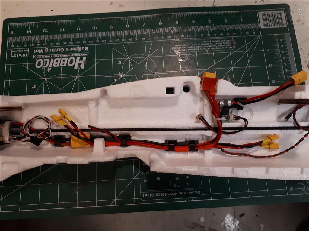


 I also added a small pdb in the rear for power to the PI and other equipment. The loom is, as yours, wired such that without the safety connector inserted there is only power to the FC, PI and aux equipment (no power to the ESCs and motors.