MAVLink and Arduino
by Juan Pedro López
This is not a post on the details of MAVLink serial protocol. If you are interested on the protocol itself, you can read the fantastic post by Pedro Alburquerque:
This post will be focused on my experience and practical use of MAVLink protocol on an on-board Arduino (Nano with ATmega328) that communicates with a Pixhawk flight controller (a clone one, v2.4.8). I am using the Arduino to control the lights of my drone (WS2812B leds) and the code you will see here is mainly focused in that direction.
Wiring all the components
You only need to connect the serial port of your Arduino to the serial port of the Pixhawk. No special requirements here, as both boards use UART interfaces.
Just remember to connect RX on one side to TX of the other side and both GND together. That’s all.
As I am going to use some WS2812B led lights, I will be feeding them directly from the PDB (Power Distribution Board) of my drone. In my case, I will be using the +5V output. All grounds connected. Signal to the leds will be taken from pin 2 of the Arduino.
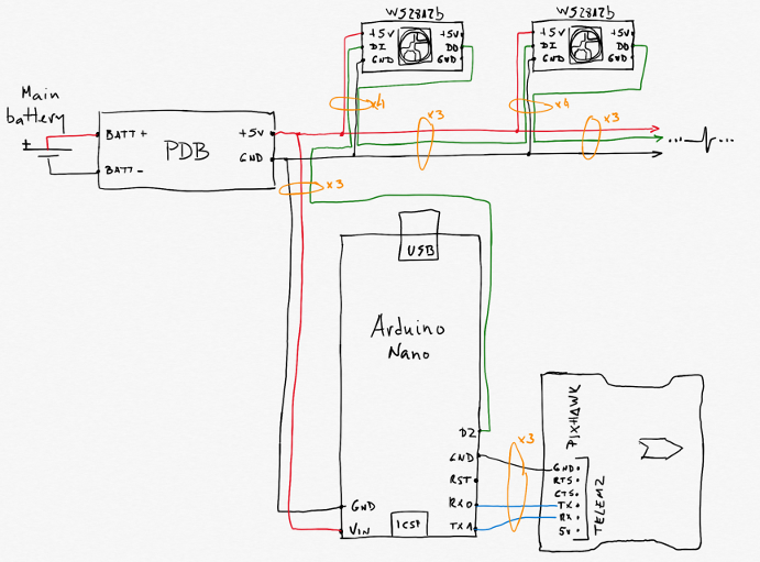
As you can see, I am taking advantage of the +5V of my PDB to power the on-board Arduino Nano through its Vin pin.
One small remark on the physical wires. I have marked in orange how I have grouped the wires to help having a clean setup. You can see I have used mostly 3xcores cables in most of the connections, and 4xcores cable from the “lights bus” to the leds. Doing this, adding as many lights as your power distribution board allows is very simple by just splicing the bus cable at any point. Please note that I have used a 3xcores cable to bring power from the PDB to the Arduino and to take the D2 lights control signal from the Arduino to the lights bus.
Step 1: install the MAVLink library in your Arduino IDE
I had many problems at the begining that were only related to an outdated version of the library I was using with the IDE.
This is the one I have been using. It was programmed by Lorenz Meier (thanks a lot!): GitHub - mavlink/mavlink: Marshalling / communication library for drones.
mavlink.zip (300.9 KB)
Once the proper library is in place, we can start the programming.
Step 2: configure the Pixhawk
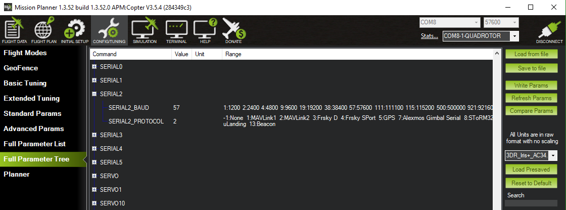
You can use any serial port on the Pixhawk to connect to the Arduino. Just select the adequate protocol in the parameter list using your favourite ground station program. I am using Mission Planner and the Telemetry2 port. I have setup MAVLink2 as the protocol to be used. Remember that you must be connected via USB to the Pixhawk to be able to see and modify parameters.
Step 3: understand the data flow
If you have everything connected, powered up and have already read Pedro’s article, you will be expecting data to be flowing from your Pixhawk to your Arduino. WRONG!
If you have just connected both boards, you will only be seeing hearbeats. This message is mainly useless, it is only to indicate that one side is alive and that you have a proper link/connection. OK, yes, you can set a timer and do something if you do not receive heartbeats for a while.
You can also send heartbeats back, but again it is useless. In my experience the Pixhawk will just ignore them!
You must also understand that the MAVLink protocol has no flow control. This means that you must keep track of what you send and the response you expect. If something is not as expected, maybe the message was lost and you will have to repeat the request.
Step 4: request data from the Pixhawk
Now that you have nice and useless heartbeats, it is time to ask for the interesting data that you need in your program. How do you do this? By requesting STREAMS!
First, configure the library in your code, then start the serial port, now be polite and send some heartbeats (I know, I told you they are useless). In the code you will see what are the parameters used for. The constants you will see are encoded in the mavlink.h library. You can see there their values and some explanations.
// Call the library
#include "mavlink.h"

// Launch the serial port in setup
void setup() {
  // MAVLink interface start
  Serial.begin(57600);

// Loop your program
void loop() {
  // MAVLink config
  /* The default UART header for your MCU */
  int sysid = 1;                   ///< ID 20 for this airplane. 1 PX, 255 ground station
  int compid = 158;                ///< The component sending the message
  int type = MAV_TYPE_QUADROTOR;   ///< This system is an airplane / fixed wing

  // Define the system type, in this case an airplane -> on-board controller
  uint8_t system_type = MAV_TYPE_GENERIC;
  uint8_t autopilot_type = MAV_AUTOPILOT_INVALID;

  uint8_t system_mode = MAV_MODE_PREFLIGHT; ///< Booting up
  uint32_t custom_mode = 0;                 ///< Custom mode, can be defined by user/adopter
  uint8_t system_state = MAV_STATE_STANDBY; ///< System ready for flight

  // Initialize the required buffers
  mavlink_message_t msg;
  uint8_t buf[MAVLINK_MAX_PACKET_LEN];

  // Pack the message
  mavlink_msg_heartbeat_pack(1,0, &msg, type, autopilot_type, system_mode, custom_mode, system_state);

  // Copy the message to the send buffer
  uint16_t len = mavlink_msg_to_send_buffer(buf, &msg);

  // Send the message with the standard UART send function
  // uart0_send might be named differently depending on
  // the individual microcontroller / library in use.
  unsigned long currentMillisMAVLink = millis();
  if (currentMillisMAVLink - previousMillisMAVLink >= next_interval_MAVLink) {
    // Timing variables
    previousMillisMAVLink = currentMillisMAVLink;

    Serial.write(buf, len);

    //Mav_Request_Data();
    num_hbs_pasados++;
    if(num_hbs_pasados>=num_hbs) {
      // Request streams from Pixhawk
      Mav_Request_Data();
      num_hbs_pasados=0;
    }
  }

  // Check reception buffer
  comm_receive();
}
Now that you have a main loop working, let’s focus on the Mav_Request_Data() function you can see by the end. No, it is not in the mavlink.h library.
This is the KEY part of the program. This function is the one telling the Pixhawk what data sets you want and at what transmission rate. You can ask for more than one type.
In my case this is the code behind it as per the streams I am interested in, you can modify it to request other streams (I leave my findings in the comments):
void Mav_Request_Data()
{
  mavlink_message_t msg;
  uint8_t buf[MAVLINK_MAX_PACKET_LEN];

  // STREAMS that can be requested
  /*
   * Definitions are in common.h: enum MAV_DATA_STREAM
   *
   * MAV_DATA_STREAM_ALL=0, // Enable all data streams
   * MAV_DATA_STREAM_RAW_SENSORS=1, /* Enable IMU_RAW, GPS_RAW, GPS_STATUS packets.
   * MAV_DATA_STREAM_EXTENDED_STATUS=2, /* Enable GPS_STATUS, CONTROL_STATUS, AUX_STATUS
   * MAV_DATA_STREAM_RC_CHANNELS=3, /* Enable RC_CHANNELS_SCALED, RC_CHANNELS_RAW, SERVO_OUTPUT_RAW
   * MAV_DATA_STREAM_RAW_CONTROLLER=4, /* Enable ATTITUDE_CONTROLLER_OUTPUT, POSITION_CONTROLLER_OUTPUT, NAV_CONTROLLER_OUTPUT.
   * MAV_DATA_STREAM_POSITION=6, /* Enable LOCAL_POSITION, GLOBAL_POSITION/GLOBAL_POSITION_INT messages.
   * MAV_DATA_STREAM_EXTRA1=10, /* Dependent on the autopilot
   * MAV_DATA_STREAM_EXTRA2=11, /* Dependent on the autopilot
   * MAV_DATA_STREAM_EXTRA3=12, /* Dependent on the autopilot
   * MAV_DATA_STREAM_ENUM_END=13,
   *
   * Data in PixHawk available in:
   *  - Battery, amperage and voltage (SYS_STATUS) in MAV_DATA_STREAM_EXTENDED_STATUS
   *  - Gyro info (IMU_SCALED) in MAV_DATA_STREAM_EXTRA1
   */

  // To be setup according to the needed information to be requested from the Pixhawk
  const int  maxStreams = 2;
  const uint8_t MAVStreams[maxStreams] = {MAV_DATA_STREAM_EXTENDED_STATUS, MAV_DATA_STREAM_EXTRA1};
  const uint16_t MAVRates[maxStreams] = {0x02,0x05};

  for (int i=0; i < maxStreams; i++) {
    /*
     * mavlink_msg_request_data_stream_pack(system_id, component_id,
     *    &msg,
     *    target_system, target_component,
     *    MAV_DATA_STREAM_POSITION, 10000000, 1);
     *
     * mavlink_msg_request_data_stream_pack(uint8_t system_id, uint8_t component_id,
     *    mavlink_message_t* msg,
     *    uint8_t target_system, uint8_t target_component, uint8_t req_stream_id,
     *    uint16_t req_message_rate, uint8_t start_stop)
     *
     */
    mavlink_msg_request_data_stream_pack(2, 200, &msg, 1, 0, MAVStreams[i], MAVRates[i], 1);
    uint16_t len = mavlink_msg_to_send_buffer(buf, &msg);
    Serial.write(buf, len);
  }
}
Please note the line that indicates the data rate in Hz (times per second) per requested data stream:
const uint16_t MAVRates[maxStreams] = {0x02,0x05};
This means I was requesting MAV_DATA_STREAM_EXTENDED_STATUS twice per second and MAV_DATA_STREAM_EXTRA1 five times per second. If I remember well, this parameter was having actual impact in the data rate I was getting from the Pixhawk. I must recognise I did not actually check the exact rate.
Step 5: listen to the streams from the Pixhawk
Now you have a lot, I repeat, a lot of data comming through your serial link with the Pixhawk. It is time to focus on what messages we are interested in and how to decode them. You have seen in the main loop this function comm_receive(). Again, it is not a library function, it is something you must write.
You MUST implement the messages you expect. The mavlink.h library provides you with primitives to the most typical messages, but it does not implement the full MAVLink protocol. Do not worry, you will probably not need anything else for “simple” implementations (like mine).
As a reference, I have left as a comment the definition of the primitive as found in the library. I think this is a much simpler to understand approach as at the beginning I had problems understanding how to implement the messages decoding.
If you need a message not in my code, you only need to look for the adequate directive and implement a new case block.
This is my code:
void comm_receive() {
mavlink_message_t msg;
mavlink_status_t status;
while(Serial.available()>0) {
uint8_t c = Serial.read();
// Try to get a new message
if(mavlink_parse_char(MAVLINK_COMM_0, c, &msg, &status)) {
// Handle message
switch(msg.msgid) {
case MAVLINK_MSG_ID_HEARTBEAT: // #0: Heartbeat
{
// E.g. read GCS heartbeat and go into
// comm lost mode if timer times out
}
break;
case MAVLINK_MSG_ID_SYS_STATUS: // #1: SYS_STATUS
{
/* Message decoding: PRIMITIVE
* mavlink_msg_sys_status_decode(const mavlink_message_t* msg, mavlink_sys_status_t* sys_status)
*/
//mavlink_message_t* msg;
mavlink_sys_status_t sys_status;
mavlink_msg_sys_status_decode(&msg, &sys_status);
}
break;
case MAVLINK_MSG_ID_PARAM_VALUE: // #22: PARAM_VALUE
{
/* Message decoding: PRIMITIVE
* mavlink_msg_param_value_decode(const mavlink_message_t* msg, mavlink_param_value_t* param_value)
*/
//mavlink_message_t* msg;
mavlink_param_value_t param_value;
mavlink_msg_param_value_decode(&msg, ¶m_value);
}
break;
case MAVLINK_MSG_ID_RAW_IMU: // #27: RAW_IMU
{
/* Message decoding: PRIMITIVE
* static inline void mavlink_msg_raw_imu_decode(const mavlink_message_t* msg, mavlink_raw_imu_t* raw_imu)
*/
mavlink_raw_imu_t raw_imu;
mavlink_msg_raw_imu_decode(&msg, &raw_imu);
}
break;
        case MAVLINK_MSG_ID_ATTITUDE:  // #30
          {
            /* Message decoding: PRIMITIVE
             *    mavlink_msg_attitude_decode(const mavlink_message_t* msg, mavlink_attitude_t* attitude)
             */
mavlink_attitude_t attitude;
mavlink_msg_attitude_decode(&msg, &attitude);
if(attitude.roll>1) leds_modo = 0;
else if(attitude.roll<-1) leds_modo = 2;
else leds_modo=1;
}
break;
default:
break;
}
}
}
}
You must have a look at how each structure is defined to later on be able to extract the detailed value you need. For instance, have a look at the decoding of message #30 in the code above on how to get the roll value from the attitude structure.
But, wait! How did I get to that information?
All messages implemented in the mavlink.h library are stored in the library itself under the \common directory. In the example above, the details on the implementation of:
case MAVLINK_MSG_ID_ATTITUDE: // #30
{
/* Message decoding: PRIMITIVE
* mavlink_msg_attitude_decode(const mavlink_message_t* msg, mavlink_attitude_t* attitude)
*/
Is in the file \common\mavlink_msg_attitude.h. At the very top of each message you have the definition of the data structure and the variables that are encoded within:
#define MAVLINK_MSG_ID_ATTITUDE 30

typedef struct __mavlink_attitude_t
{
 uint32_t time_boot_ms; ///< Timestamp (milliseconds since system boot)
 float roll; ///< Roll angle (rad)
 float pitch; ///< Pitch angle (rad)
 float yaw; ///< Yaw angle (rad)
 float rollspeed; ///< Roll angular speed (rad/s)
 float pitchspeed; ///< Pitch angular speed (rad/s)
 float yawspeed; ///< Yaw angular speed (rad/s)
} mavlink_attitude_t;
As you can see, now you only need to name the variable to have full access. In this message you get: roll, pitch, yaw, rollspeed, pitchspeed and yawspeed.
How to use it all
And this is the full program, my current working version with lots of information as a reference for future functionalities to be implemented. I am using the Arduino to control some lights on board.
You will see I was using some debugging via Softwareserial libary. With this setup I could relay data to a second Arduino board as an interface with the PC. In this setup, the Pixhawk was not connected to the serial port of the Arduino, but to pins 9 and 10 as a softserial port.
And if you have any comments, please contact me!
/* MAVLInk_DroneLights
* by Juan Pedro López
*
* This program was developed to connect an Arduino board with a Pixhawk via MAVLink
* with the objective of controlling a group of WS2812B LED lights on board of a quad
*
* The current version of the program is working properly.
*
* TO DO:
* - Move STREAMS request to RC_CHANNELS to use values in logic
* - Add RC_CHANNLES_RAW messages monitoring: move #30 to RC_CHANNELS_RAW (#35)
* http://mavlink.org/messages/common#RC_CHANNELS_RAW
* - Look for message on low battery:
* To be tested: http://mavlink.org/messages/common#PARAM_REQUEST_READ
* To be checked: http://mavlink.org/messages/common#SYS_STATUS
* - Potential implementation of other alarms, like high intensity
*
* You can restrict the maximum package size with this parameter in mavlink_types.h:
#ifndef MAVLINK_MAX_PAYLOAD_LEN_
// it is possible to override this, but be careful! Defa_
#define **MAVLINK_MAX_PAYLOAD_LEN 255 ///< Maximum payload length_
#endif_
*/
// In case we need a second serial port for debugging
#define SOFT_SERIAL_DEBUGGING // Comment this line if no serial debugging is needed
#ifdef SOFT_SERIAL_DEBUGGING
// Library to use serial debugging with a second board
#include <SoftwareSerial.h>
SoftwareSerial mySerial(11, 12); // RX, TX
SoftwareSerial pxSerial(9,10); // RX, TX
#endif
#include "FastLED.h"
#include "mavlink.h"
//#include "common/mavlink_msg_request_data_stream.h"
// Mavlink variables
unsigned long previousMillisMAVLink = 0; // will store last time MAVLink was transmitted and listened
unsigned long next_interval_MAVLink = 1000; // next interval to count
const int num_hbs = 60; // # of heartbeats to wait before activating STREAMS from Pixhawk. 60 = one minute.
int num_hbs_pasados = num_hbs;
// FastLed setup
// How many leds in your strip?
#define NUM_LEDS 8
#define BRIGHTNESS 255 // Put 0 to switch off all leds
// For led chips like Neopixels, which have a data line, ground, and power, you just
// need to define DATA_PIN. For led chipsets that are SPI based (four wires - data, clock,
// ground, and power), like the LPD8806 define both DATA_PIN and CLOCK_PIN
#define DATA_PIN 2
//#define MODE_PIN 3
//#define CLOCK_PIN 13
// Define the array of leds
CRGB leds[NUM_LEDS];
// Status: 0, 2, 4 for lights off, 1, 3 for lights on
// Pulses: flashing with two 20 ms pulses, 80 ms in between pulses and 1 Hz frequency
int leds_status = 0;
// Light modes: 1, normal mode. 0, off. 2, low battery.
#define NUM_MODOS 3
int leds_modo = 1;
// Definición de las matrices ON y OFF de los modos
CRGB led_on[NUM_MODOS][NUM_LEDS] = {
// Mode 0
{
CRGB::White, // Warning: test values
CRGB::Black,
CRGB::Black,
CRGB::Black,
CRGB::Black,
CRGB::Black,
CRGB::Black,
CRGB::Black
},
// Mode 1
{
CRGB::White, // Warning: test values
CRGB::White,
CRGB::Red,
CRGB::Green,
CRGB::White,
CRGB::White,
CRGB::Red,
CRGB::Red
},
// Mode 2
{
CRGB::Blue, // Warning: test values
CRGB::White,
CRGB::Red,
CRGB::Green,
CRGB::White,
CRGB::White,
CRGB::Red,
CRGB::Red
}
};
CRGB led_off[NUM_MODOS][NUM_LEDS] = {
// Mode 0
{
CRGB::Blue, // Static
CRGB::Black, // Static
CRGB::Black, // Static
CRGB::Black, // Static
CRGB::Black, // Pulses
CRGB::Black, // Pulses
CRGB::Black, // Pulses
CRGB::Black // Pulses
},
// Mode 1
{
CRGB::Black, // Static
CRGB::White, // Static
CRGB::Red, // Static
CRGB::Green, // Static
CRGB::Black, // Pulses
CRGB::Black, // Pulses
CRGB::Black, // Pulses
CRGB::Black // Pulses
},
// Mode 2
{
CRGB::Black, // Static
CRGB::White, // Static
CRGB::Black, // Static
CRGB::Black, // Static
CRGB::Black, // Pulses
CRGB::Black, // Pulses
CRGB::Black, // Pulses
CRGB::Black // Pulses
}
};
// Lights flashing adjustment
unsigned long previousMillis = 0; // will store last time LED was updated
unsigned long next_interval = 0; // next interval
const long tiempo_on = 20;
const long tiempo_off = 80;
const long tiempo_descanso = 880;
int test_led_tipo = 4;
void setup() {
// MAVLink interface start
Serial.begin(57600);
// LEDs setup
//delay(5000); // sanity delay
FastLED.addLeds<WS2811, DATA_PIN, GRB>(leds, NUM_LEDS);
FastLED.setBrightness( BRIGHTNESS );
#ifdef SOFT_SERIAL_DEBUGGING
// [DEB] Soft serial port start
Serial.begin(57600);
Serial.println("MAVLink starting.");
mySerial.begin(57600);
#endif
}
void loop() {
// Lights management
// Light pulses: 2 quick flashes per second. 100 ms each cycle
unsigned long currentMillis = millis();
int i=0;
// Normal mode, lights on.
if (currentMillis - previousMillis >= next_interval) {
// Keep time last mode changed
previousMillis = currentMillis;
// Toggle lights depending on status
switch (leds_status){
case 0:
{
next_interval=tiempo_on;
for(i=0;i<NUM_LEDS;i++){
leds[i]=led_on[leds_modo][i];
}
break;
}
case 1:
{
next_interval=tiempo_off;
for(i=0;i<NUM_LEDS;i++){
leds[i]=led_off[leds_modo][i];
}
break;
}
case 2:
{
next_interval=tiempo_on;
for(i=0;i<NUM_LEDS;i++){
leds[i]=led_on[leds_modo][i];
}
break;
}
case 3:
{
next_interval=tiempo_descanso;
for(i=0;i<NUM_LEDS;i++){
leds[i]=led_off[leds_modo][i];
}
break;
}
}
// Show leds
FastLED.show();
// Cycle status from 0 to 3
leds_status++;
if(leds_status >= 4) leds_status=0;
}
// MAVLink
/* The default UART header for your MCU */
int sysid = 1; ///< ID 20 for this airplane. 1 PX, 255 ground station
int compid = 158; ///< The component sending the message
int type = MAV_TYPE_QUADROTOR; ///< This system is an airplane / fixed wing
// Define the system type, in this case an airplane -> on-board controller
// uint8_t system_type = MAV_TYPE_FIXED_WING;
uint8_t system_type = MAV_TYPE_GENERIC;
uint8_t autopilot_type = MAV_AUTOPILOT_INVALID;
uint8_t system_mode = MAV_MODE_PREFLIGHT; ///< Booting up
uint32_t custom_mode = 0; ///< Custom mode, can be defined by user/adopter
uint8_t system_state = MAV_STATE_STANDBY; ///< System ready for flight
// Initialize the required buffers
mavlink_message_t msg;
uint8_t buf[MAVLINK_MAX_PACKET_LEN];
// Pack the message
//mavlink_msg_heartbeat_pack(sysid,compid, &msg, type, autopilot_type, system_mode, custom_mode, system_state);
mavlink_msg_heartbeat_pack(1,0, &msg, type, autopilot_type, system_mode, custom_mode, system_state);
// Copy the message to the send buffer
uint16_t len = mavlink_msg_to_send_buffer(buf, &msg);
// Send the message with the standard UART send function
// uart0_send might be named differently depending on
// the individual microcontroller / library in use.
unsigned long currentMillisMAVLink = millis();
if (currentMillisMAVLink - previousMillisMAVLink >= next_interval_MAVLink) {
// Guardamos la última vez que se cambió el modo
previousMillisMAVLink = currentMillisMAVLink;
#ifdef SOFT_SERIAL_DEBUGGING
pxSerial.write(buf,len);
//mySerial.println("Ardu HB");
#else
Serial.write(buf, len);
#endif
//Mav_Request_Data();
num_hbs_pasados++;
if(num_hbs_pasados>=num_hbs) {
// Request streams from Pixhawk
#ifdef SOFT_SERIAL_DEBUGGING
mySerial.println("Streams requested!");
#endif
Mav_Request_Data();
num_hbs_pasados=0;
}
}
// Check reception buffer
comm_receive();
}
void Mav_Request_Data()
{
mavlink_message_t msg;
uint8_t buf[MAVLINK_MAX_PACKET_LEN];
// STREAMS that can be requested
/*
* Definitions are in common.h: enum MAV_DATA_STREAM
*
* MAV_DATA_STREAM_ALL=0, // Enable all data streams
* MAV_DATA_STREAM_RAW_SENSORS=1, /* Enable IMU_RAW, GPS_RAW, GPS_STATUS packets.
* MAV_DATA_STREAM_EXTENDED_STATUS=2, /* Enable GPS_STATUS, CONTROL_STATUS, AUX_STATUS
* MAV_DATA_STREAM_RC_CHANNELS=3, /* Enable RC_CHANNELS_SCALED, RC_CHANNELS_RAW, SERVO_OUTPUT_RAW
* MAV_DATA_STREAM_RAW_CONTROLLER=4, /* Enable ATTITUDE_CONTROLLER_OUTPUT, POSITION_CONTROLLER_OUTPUT, NAV_CONTROLLER_OUTPUT.
* MAV_DATA_STREAM_POSITION=6, /* Enable LOCAL_POSITION, GLOBAL_POSITION/GLOBAL_POSITION_INT messages.
* MAV_DATA_STREAM_EXTRA1=10, /* Dependent on the autopilot
* MAV_DATA_STREAM_EXTRA2=11, /* Dependent on the autopilot
* MAV_DATA_STREAM_EXTRA3=12, /* Dependent on the autopilot
* MAV_DATA_STREAM_ENUM_END=13,
*
* Data in PixHawk available in:
* - Battery, amperage and voltage (SYS_STATUS) in MAV_DATA_STREAM_EXTENDED_STATUS
* - Gyro info (IMU_SCALED) in MAV_DATA_STREAM_EXTRA1
*/
// To be setup according to the needed information to be requested from the Pixhawk
const int maxStreams = 2;
const uint8_t MAVStreams[maxStreams] = {MAV_DATA_STREAM_EXTENDED_STATUS, MAV_DATA_STREAM_EXTRA1};
const uint16_t MAVRates[maxStreams] = {0x02,0x05};
for (int i=0; i < maxStreams; i++) {
/*
* mavlink_msg_request_data_stream_pack(system_id, component_id,
* &msg,
* target_system, target_component,
* MAV_DATA_STREAM_POSITION, 10000000, 1);
*
* mavlink_msg_request_data_stream_pack(uint8_t system_id, uint8_t component_id,
* mavlink_message_t* msg,
* uint8_t target_system, uint8_t target_component, uint8_t req_stream_id,
* uint16_t req_message_rate, uint8_t start_stop)
*
*/
mavlink_msg_request_data_stream_pack(2, 200, &msg, 1, 0, MAVStreams[i], MAVRates[i], 1);
uint16_t len = mavlink_msg_to_send_buffer(buf, &msg);
#ifdef SOFT_SERIAL_DEBUGGING
pxSerial.write(buf,len);
#else
Serial.write(buf, len);
#endif
}
// Request: PARAM_REQUEST_LIST. Only for full log recording
/*
* Primitive: mavlink_msg_param_request_list_pack(uint8_t system_id, uint8_t component_id, mavlink_message_t* msg,
uint8_t target_system, uint8_t target_component)
*/
/*
// Configure
uint8_t system_id=2;
uint8_t component_id=200;
// mavlink_message_t* msg;
uint8_t target_system=1;
uint8_t target_component=0;
// Pack
mavlink_msg_param_request_list_pack(system_id, component_id, &msg,
target_system, target_component);
uint16_t len = mavlink_msg_to_send_buffer(buf, &msg);
// Send
#ifdef SOFT_SERIAL_DEBUGGING
pxSerial.write(buf,len);
#else
Serial.write(buf, len);
#endif
*/
}
void comm_receive() {
mavlink_message_t msg;
mavlink_status_t status;
// Echo for manual debugging
// Serial.println("---Start---");
#ifdef SOFT_SERIAL_DEBUGGING
while(pxSerial.available()>0) {
uint8_t c = pxSerial.read();
#else
while(Serial.available()>0) {
uint8_t c = Serial.read();
#endif
// Try to get a new message
if(mavlink_parse_char(MAVLINK_COMM_0, c, &msg, &status)) {
// Handle message
switch(msg.msgid) {
case MAVLINK_MSG_ID_HEARTBEAT: // #0: Heartbeat
{
// E.g. read GCS heartbeat and go into
// comm lost mode if timer times out
#ifdef SOFT_SERIAL_DEBUGGING
//mySerial.println("PX HB");
#endif
}
break;
case MAVLINK_MSG_ID_SYS_STATUS: // #1: SYS_STATUS
{
/* Message decoding: PRIMITIVE
* mavlink_msg_sys_status_decode(const mavlink_message_t* msg, mavlink_sys_status_t* sys_status)
*/
//mavlink_message_t* msg;
mavlink_sys_status_t sys_status;
mavlink_msg_sys_status_decode(&msg, &sys_status);
#ifdef SOFT_SERIAL_DEBUGGING
mySerial.print("PX SYS STATUS: ");
mySerial.print("[Bat (V): ");
mySerial.print(sys_status.voltage_battery);
mySerial.print("], [Bat (A): ");
mySerial.print(sys_status.current_battery);
mySerial.print("], [Comms loss (%): ");
mySerial.print(sys_status.drop_rate_comm);
mySerial.println("]");
#endif
}
break;
case MAVLINK_MSG_ID_PARAM_VALUE: // #22: PARAM_VALUE
{
/* Message decoding: PRIMITIVE
* mavlink_msg_param_value_decode(const mavlink_message_t* msg, mavlink_param_value_t* param_value)
*/
//mavlink_message_t* msg;
mavlink_param_value_t param_value;
mavlink_msg_param_value_decode(&msg, ¶m_value);
#ifdef SOFT_SERIAL_DEBUGGING
mySerial.println("PX PARAM_VALUE");
mySerial.println(param_value.param_value);
mySerial.println(param_value.param_count);
mySerial.println(param_value.param_index);
mySerial.println(param_value.param_id);
mySerial.println(param_value.param_type);
mySerial.println("------ Fin -------");
#endif
}
break;
case MAVLINK_MSG_ID_RAW_IMU: // #27: RAW_IMU
{
/* Message decoding: PRIMITIVE
* static inline void mavlink_msg_raw_imu_decode(const mavlink_message_t* msg, mavlink_raw_imu_t* raw_imu)
*/
mavlink_raw_imu_t raw_imu;
mavlink_msg_raw_imu_decode(&msg, &raw_imu);
#ifdef SOFT_SERIAL_DEBUGGING
//mySerial.println("PX RAW IMU");
//mySerial.println(raw_imu.xacc);
#endif
}
break;
case MAVLINK_MSG_ID_ATTITUDE: // #30
{
/* Message decoding: PRIMITIVE
* mavlink_msg_attitude_decode(const mavlink_message_t* msg, mavlink_attitude_t* attitude)
*/
mavlink_attitude_t attitude;
mavlink_msg_attitude_decode(&msg, &attitude);
#ifdef SOFT_SERIAL_DEBUGGING
//mySerial.println("PX ATTITUDE");
//mySerial.println(attitude.roll);
if(attitude.roll>1) leds_modo = 0;
else if(attitude.roll<-1) leds_modo = 2;
else leds_modo=1;
#endif
}
break;
default:
#ifdef SOFT_SERIAL_DEBUGGING
mySerial.print("--- Otros: ");
mySerial.print("[ID: ");
mySerial.print(msg.msgid);
mySerial.print("], [seq: ");
mySerial.print(msg.seq);
mySerial.println("]");
#endif
break;
}
}
}
}
To be added to this post
I have been exchanging some PMs (Private Messages) with some users who asked me things I didn’t know when I wrote this post. I will be modifying the post whenever I have some time spare to try to keep the tutorial structure so that you only dig if you really need to.
For the moment, three main topics have arisen, if you need urgent advise on how to implement any, please PM me.
Debugging
How to divert MAVLink comms to a SoftwareSerial port so that you can use the UART and the Serial Monitor in the Arduino IDE to interact with the board while having active MAVLink with the flight controller.
In principle, the mavlink.h library is not implementing any communications, it jus relies on the standard Serial port commands. Thus, you can just create a SoftwareSerial port on a different pair of pins and then use that port to send the information. Doing so you can then use the serial port to send and receive info using the Serial Monitor.
What streams to request
I have not been able to find any clear information on the mapping of what streams are linked to what messages. But, now I have found the code of the Pixhawk where this mapping is implemented in arducopter: ardupilot/ArduCopter/GCS_Mavlink.cpp at f8d5fe96d8b7fa9d4340b280b748e158cb593af7 · ArduPilot/ardupilot · GitHub. Chek lines 574 to 654.
I want to process it to try to build a table to link every stream with every message answered back and the file of the mavlink.h library where the message is implemented.
Routing
I was wrong, I thought the Pixhawk was not routing messages between its ports. After a comment I received from @newts and a PM he sent to me where he sent me a link to this page.
This is pretty new and still working wiht it. If I am able to reach to any conclussions, I will also include them in the post.


