Hi all,
We’re DADA Technology, a small hardware team building 30.5x30.5mm flight controllers for racing and long-range rigs. This is our first post here, so I want to do it properly: a full hardware walkthrough of our D-H743 board, the wiring diagram, what each part does and why we picked it — and at the end, a request for guidance on contributing an ArduPilot board definition, because that’s where we want this board to end up.
Why we designed this board
Before the part-by-part walkthrough, here were the design goals we laid out at the start:
- Direct 3-6S battery input (12-25.2V), so a 6S long-range rig doesn’t need a separate BEC board in the stack
- Enough onboard logging flash to survive a whole tuning day — 128MB BlackBox instead of the 16MB that is still common on this size of board
- Gyro flexibility — a battle-proven MPU6000 as the standard sensor, with two optional BMI270 positions for pilots who want dual-IMU redundancy
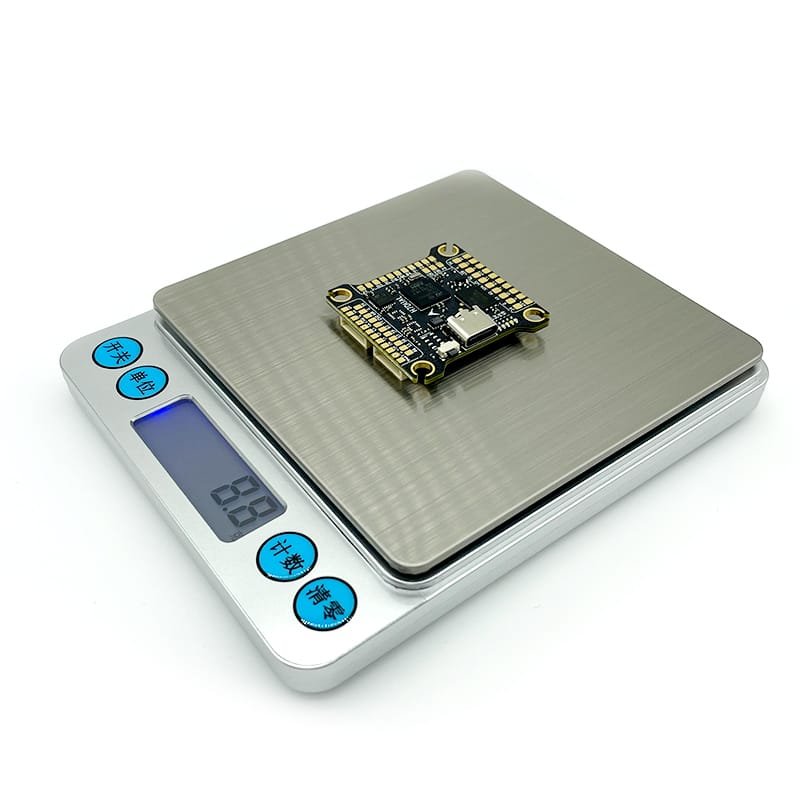
- Stay small and light: 37x37mm, 8.8g, standard 30.5x30.5mm mounting
The MCU choice was deliberate. The STM32H743 is the same Cortex-M7 family that ArduPilot already runs on in other flight controllers, so there is a mature code path for it. We picked it partly because we want this board to run ArduPilot properly, not just Betaflight.
Board walkthrough
[IMAGE 2]
MCU — STM32H743VIH6 (Cortex-M7). This is the brain of the board. The reason it matters for ArduPilot users is headroom: the faster core leaves plenty of margin for the filter chain, high-rate logging and the EKF at the same time, instead of forcing you to trade one against another. It also means the board won’t be the limiting factor as firmware features keep growing.
Gyroscope — one MPU6000 standard, two optional BMI270s. The MPU6000 is one of the most battle-proven gyros in ArduPilot builds — well understood, well supported, predictable noise behaviour. The two additional BMI270 positions are there for pilots who want to run dual IMUs: two independent sensors means you can cross-check readings, which helps diagnose frame vibration and keeps the attitude estimate cleaner on noisy frames.
Barometer — BMP280 standard, with DPS310 or MS5611 as options. All three are supported choices; the trade-off is between cost and altitude resolution. For missions where altitude hold matters more than racing, the MS5611 is still a favourite. We left the choice to the builder rather than hard-wiring one part.
BlackBox — 128MB onboard flash. This is 8x the 16MB you still find on many boards this size. In practice it’s the difference between wiping logs between flights and keeping a full day of tuning sessions on the board, so when you go back to compare PID passes, the data is still there.
Power — direct 3-6S input, two regulated output rails (5V/2A and 5.9V/3A). One rail powers the flight controller and receiver-class peripherals, the beefier rail is sized for video gear. The wiring diagram below shows the recommended split.
Motor outputs — 8. Enough for a quad with redundancy, or octo configurations. The M1-M8 pads sit on the underside of the stack, pairing directly with a 4-in-1 ESC bottom board.
Wiring
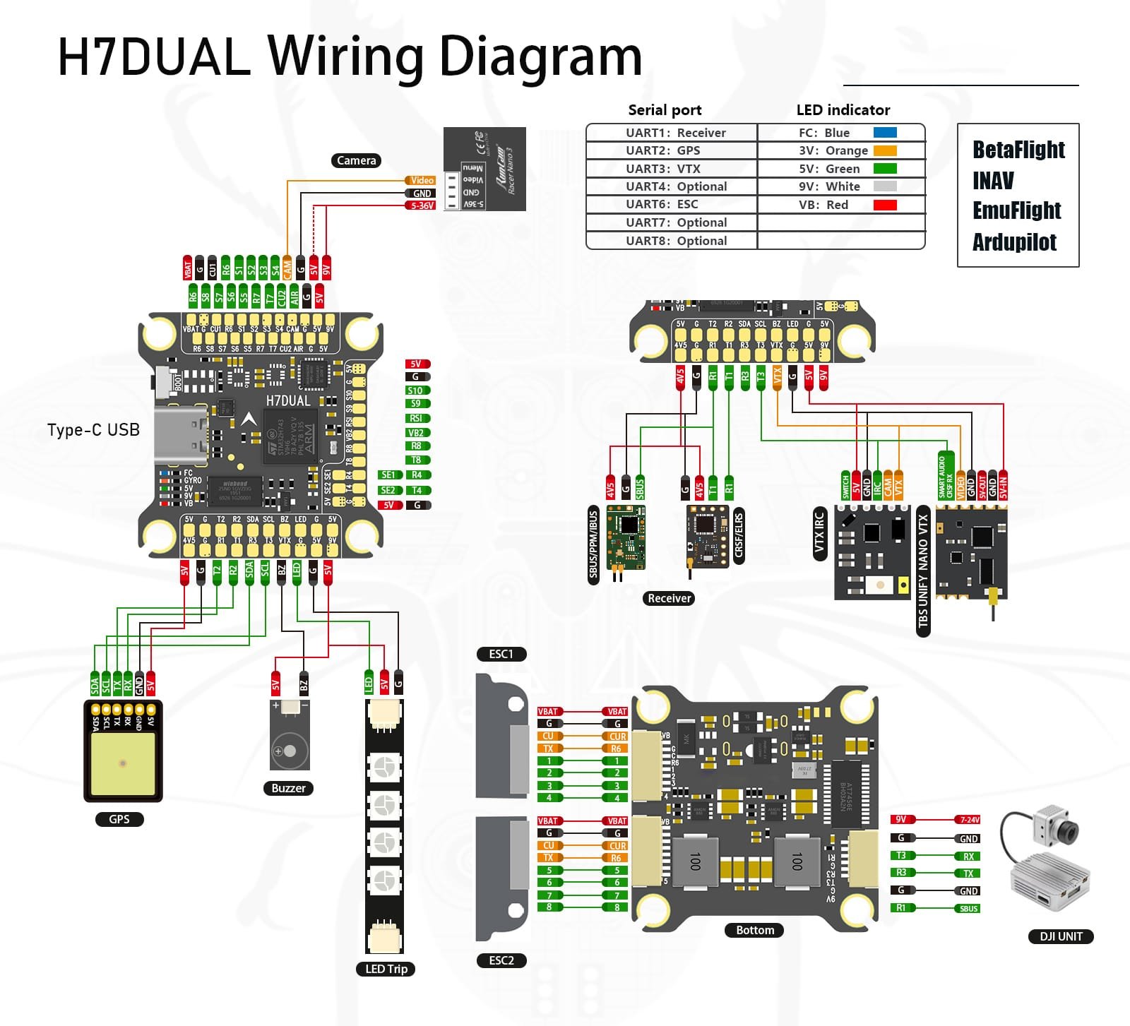
The wiring diagram is the single most useful document we publish for this board — every pad, port and power rail is on it. The default UART assignments are:
| Port | Default assignment |
|---|---|
| UART1 | Receiver |
| UART2 | GPS |
| UART3 | VTX |
| UART4 | Free |
| UART6 | 4-in-1 ESC |
| UART7 / UART8 | Free |
[IMAGE 3]
Both digital (DJI-class) and analog video links are shown as options on the diagram, so the same board serves an HD build or a cheap analog rig without rewiring the stack. There are three USER pads on the layout: one for the onboard Bluetooth enable switch, one for camera-input switching when you run more than one camera, and one general-purpose IO. The LED status behaviour table is printed on the diagram as well, so field diagnosis doesn’t require a laptop.
[IMAGE 4]
Firmware status today
In Betaflight Configurator, the board flies today on the RCH7DUAL target, and iNav is supported as well. The wiring diagram lists EmuFlight and ArduPilot as targets for this hardware — and that brings me to the honest reason for this thread.
The ArduPilot part — and what we’re asking
There is currently no board definition for this flight controller in the ArduPilot tree. We’ve read through the dev docs and searched the hwdef directory, and the closest existing definition to our hardware appears to be Aocoda-RC-H743Dual — same H743 MCU and a dual-IMU layout, which looks like a sensible starting template.
Our intended plan:
- Adapt an hwdef from the closest existing board definition
- Build and validate the bootloader
- Test on real aircraft and publish the .bin flight logs from those tests
- Submit the PR together with documentation
What we’d like from this community before we start:
- Is Aocoda-RC-H743Dual the right template to base on, or is there a better-maintained H743 definition we should start from instead?
- Beyond the developer docs, is there a checklist for vendors contributing a new board that we should follow?
- Would any maintainer be willing to test on real hardware? We can ship sample boards to make that easy.
Happy to answer any questions about the hardware in this thread — that’s what the category is for.
Zxiong Shi
DADA Technology