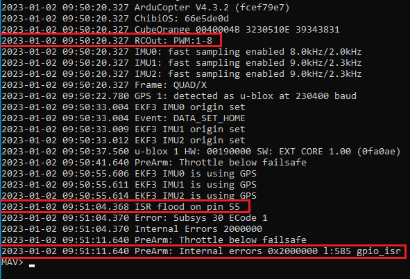
I decided to run some additional tests to troubleshoot the ISR Flood that’s happening when I use my camera’s hot-shoe.
From the posts and GitHub Bug Reports, reports of this problem have been attributed to misconfig issues - essentially two functions trying to control a single GPIO pin.
I have been using Dshot on Aux-1 through Aux-4. Since the hot-shoe input has to be on an Aux port, I thought I’d try disabling Dshot and configuring PWM motors on Main-1 through Main-4.
I’m using Main-8 as the GPIO relay for the camera shutter, and Aux-6 for the hot-shoe input.
Unfortunately, even without Dshot the result of an ISR flood are the same.
I did a test by disconnecting the hot-shoe lead. There is no ISR flood with it is disconnected. With the hot-shoe lead re-connected, I tried CAM_FEEDBACK_POL both at “0” and “1” for sensing HIGH or LOW signal. No difference in the results - both cause the ISR Flood on GPIO Pin-55.
If this issue is caused by a misconfig, I’m at a loss as to what other function might be competing for GPIO Pin-55.
Two additional notes:
I set SERVO(n)_FUNCTION=-1 for all servos except 1-4 where the PWM motors. The MAVLINK log however, still reports PWM 1-8. This looks like a bug to me - especially since I’m using Main-8 as my GPIO camera shutter relay.
Even though the wiki implies that this parameter is now redundant, I’ve tried setting SERVO_GPIO_MASK to enable GPOI on all non PWM ports - and no ports at all. It didn’t make any difference.
Does this mean the hot-shoe output from the camera is operating irregularly?
No problem getting a resistor and adding it to the harness - but not having much electronics expertise, I’ll need some guidance to try this.
What sort of resistance (or range) should I use? I’m assuming an old fashioned 1/4 watt resister like the one’s I used to get from Radio Shack will do. (or are in my electronics junk drawer)
How should it be added? Right now there’s just a single hot-shoe lead from the camera that I connect to the Aux-port signal pin. Should the resistor be in-line with that? Or should the resistor be connected between that Aux-port’s signal and ground pins?
I apologize if this is remedial. Once I get this resolved I’ll do my best to pay it forward with good documentation so you don’t have to repeat yourself.
10K ohms is the go to value, you want it either between the signal and ground or the signal and 3.3/5v. It depends if its a active low or active high signal. You could just try both.
It is possible the camera does do its own pull up / pull down, but it is not powered/active at boot. In that case a soft reboot might be enough to clear the error.
In general hardware fixes are better than software ones, however if it is just a boot order thing it would be nice for AP to recover and re-enable the pins occasionally to see if the flood has stopped.
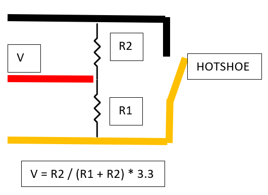
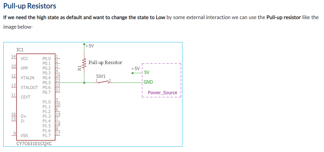
@jstroup1986, Depending on your servo rail voltage, I think you need to “pull up” your pin so that the hotshoe feedback event pulls the pin down to ground voltage. Depending on your servo rail voltage, this diagram may help
Anyone, please correct me if I’m wrong.
A 10 ohm resister between signal and ground is easy enough.
A resistor from the signal to 3.3/5v might be problematic - as I don’t apply power to the servo rail. So I wouldn’t know where to get the 3.5/5v.
The camera is powered directly from an 8.4V UBEC.
If it’s necessary or advisable, I could route the 8.4V output from the UBEC to the servo rail, and power the camera from that.
I don’t normally have power on the servo rail. And the few times I have, it’s always been just 5V to power a SiK radio. I know there’s a range of voltages the servo rail can handle - but it’s seemed safer to just power directly from the UBEC. And this camera requires 8.4V.
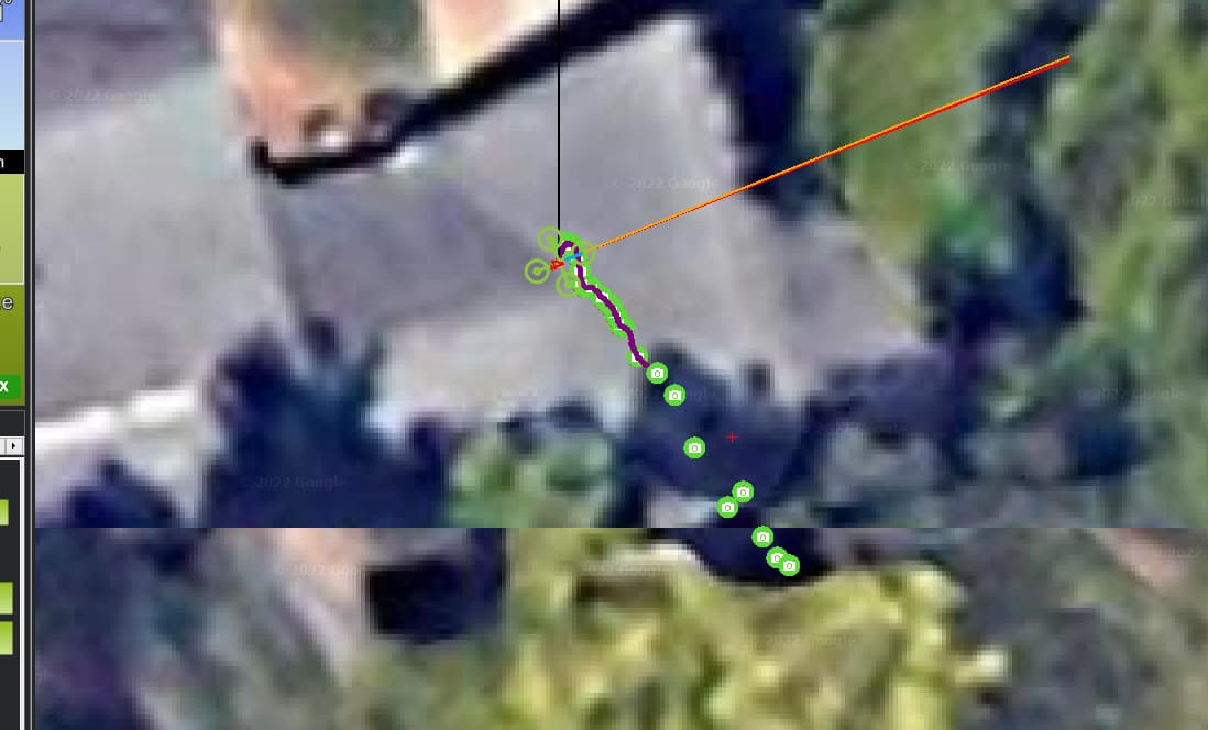
Regarding recovery, I’ve discovered that if I operate the shutter at longer intervals - say every 15-20 seconds, the hot-shoe input works a few more times. Clicking the shutter every 2-5 seconds and it fails after no more than 2 inputs received. I’ve gotten as many as 5 input received before failing when operating the shutter at longer intervals.
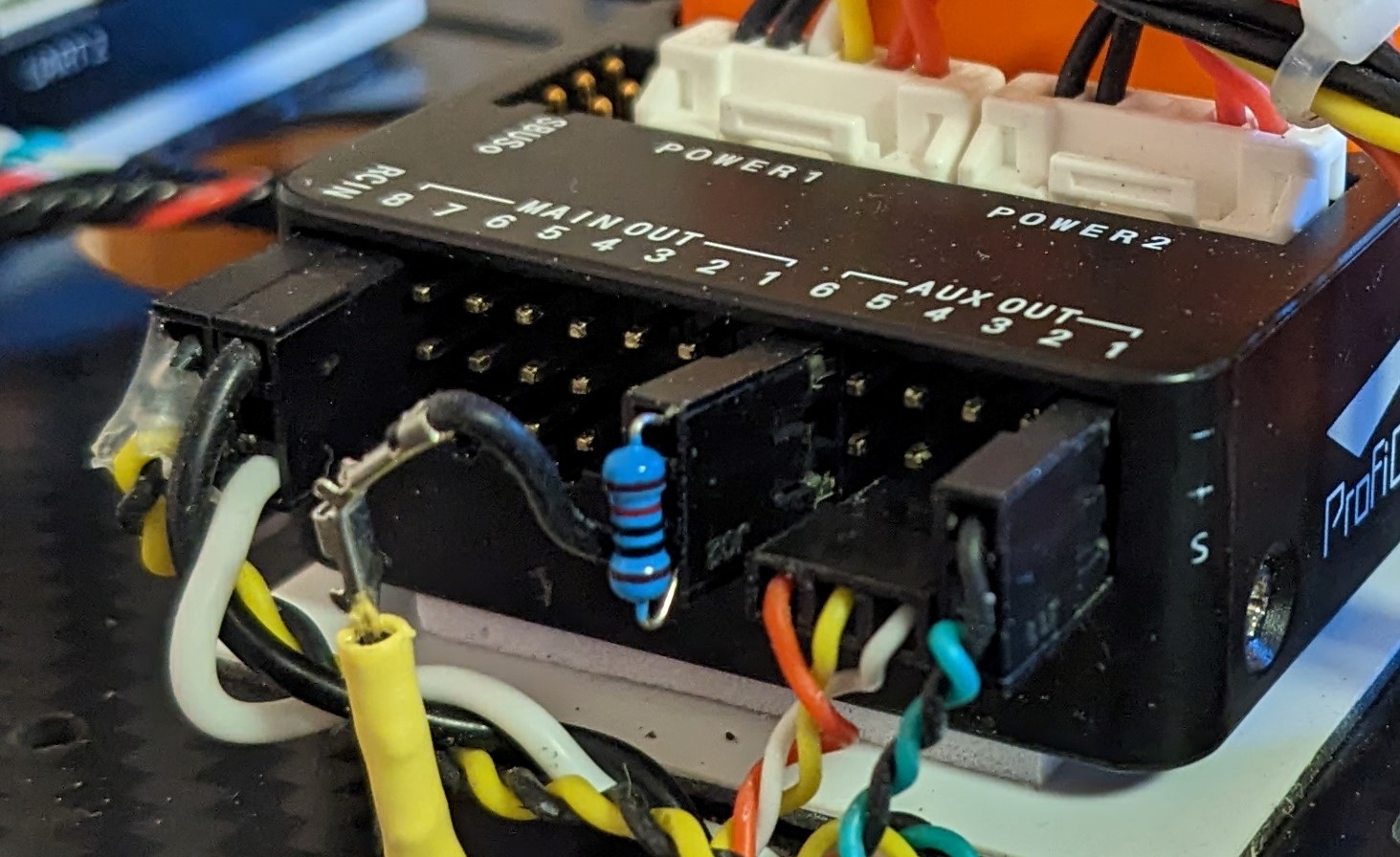
OK - with the aid of some 10K ohm resistors, I’ve now tried the hot-shoe in both pull-down and pull-up configurations.
I’m sad to report - this has not diminished the ISR Flood problem.
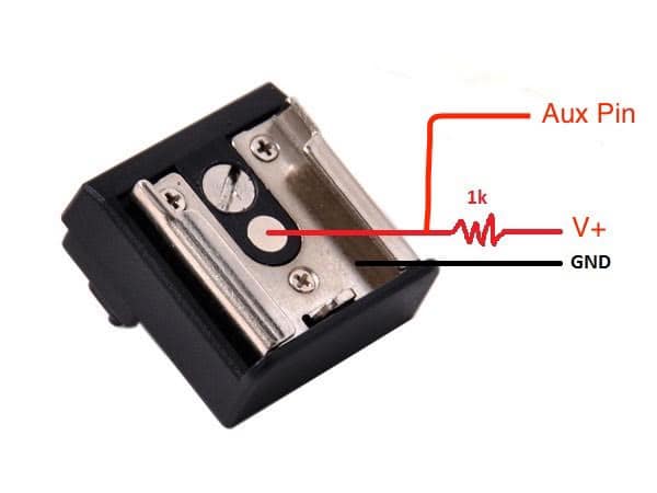
I don’t know how sensitive the pull-up or pull-down resistor is to the actual resistance. Shawn Bell offered that he’s followed this drawing that he said used to be in the ArduPilot wiki - it shows 1K ohm in a pull-up configuration.
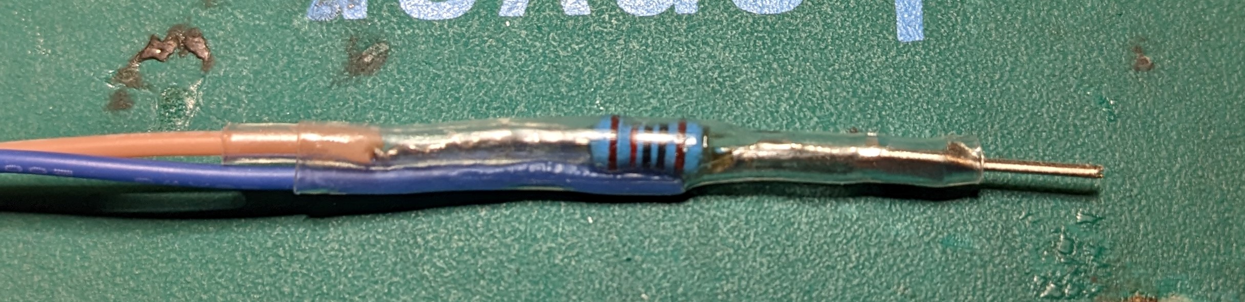
Following your advice to use 10K resistors I fabricated this rig for the pull-down configuration - where the hot-shoe lead is connected to the servo-rail ground via the resistor.
And for the pull-up configuration I fabricated this rig - that connects to the hot-shoe lead, and then the blue wire goes directly to the Aux port, and the red wire goes through the resistor and on to the Vcc of the UBEC that’s powering the camera. (it’s 8.4V)
Just for grins, I’ll probably try a pull-down resistor tomorrow and see what I can learn.
I hope I didn’t just miss something in the wiki about the need for this sort of thing. It took less than an hour to implement, but took hours of my time and a bit of time from those gracious volunteer advisors such as you - to figure out what was needed and why.
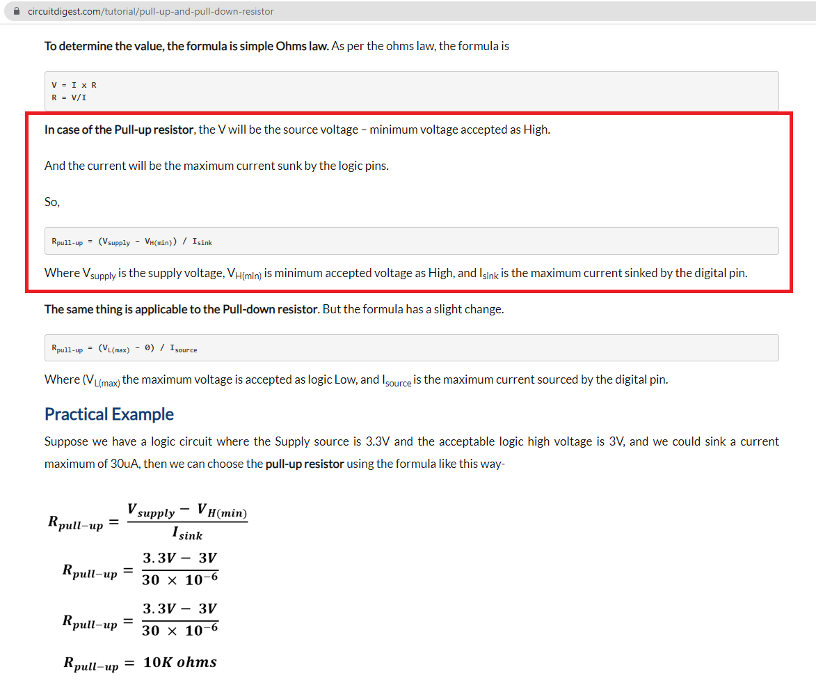
I wonder what the best way might be to find the current and voltage values in this formula for an Orange Cube - so the exact value for the resistance can be calculated.
This article saved me the trouble - I thought it was quite informative.
It explains when a pull-up or pull-down resistor is needed - and why.
It also explains how to calculate the value of the resistor - but without knowing the values on the Cube, we have to rely on experience and the fact that there is some leeway.