I’ve had some trouble with fairly slow GPS fix and sometimes the reported position drifts 50 meters or more after the fix is good enough to turn on the green LED. Only very rarely would the ground station report a 3D+DGPS fix. I had similar problems with my home built quad before I moved the GPS to a short mast to get it away from the other electronics. This post details a couple of things I have done and learned so far in an effort to improve GPS performance on the Sky Viper.
A: If you fly topless by removing the top cover to save 3 grams of weight, don’t be tempted protect the GPS module from the elements by covering it with a piece of tape. Surprisingly, tape on the antenna seems to reduce performance. I believe that this is because the ceramic antenna can be detuned a bit by the additional dielectric on the antenna surface.
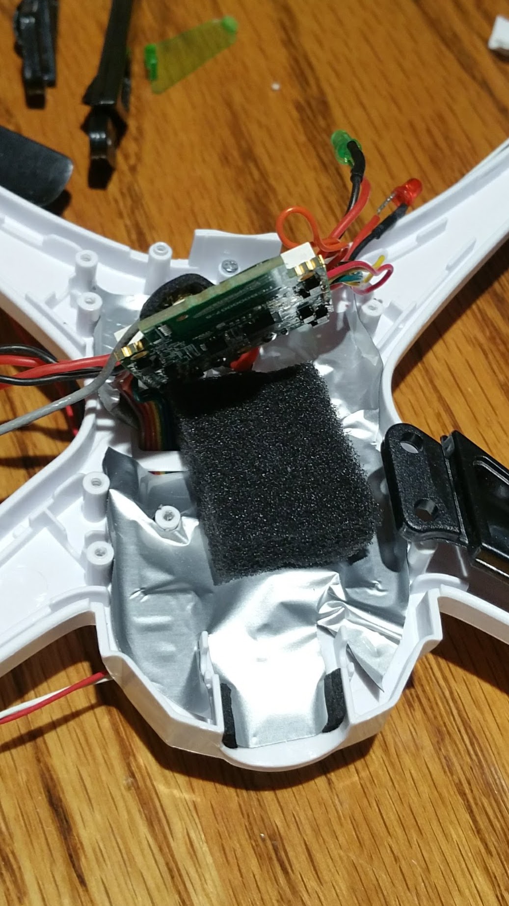
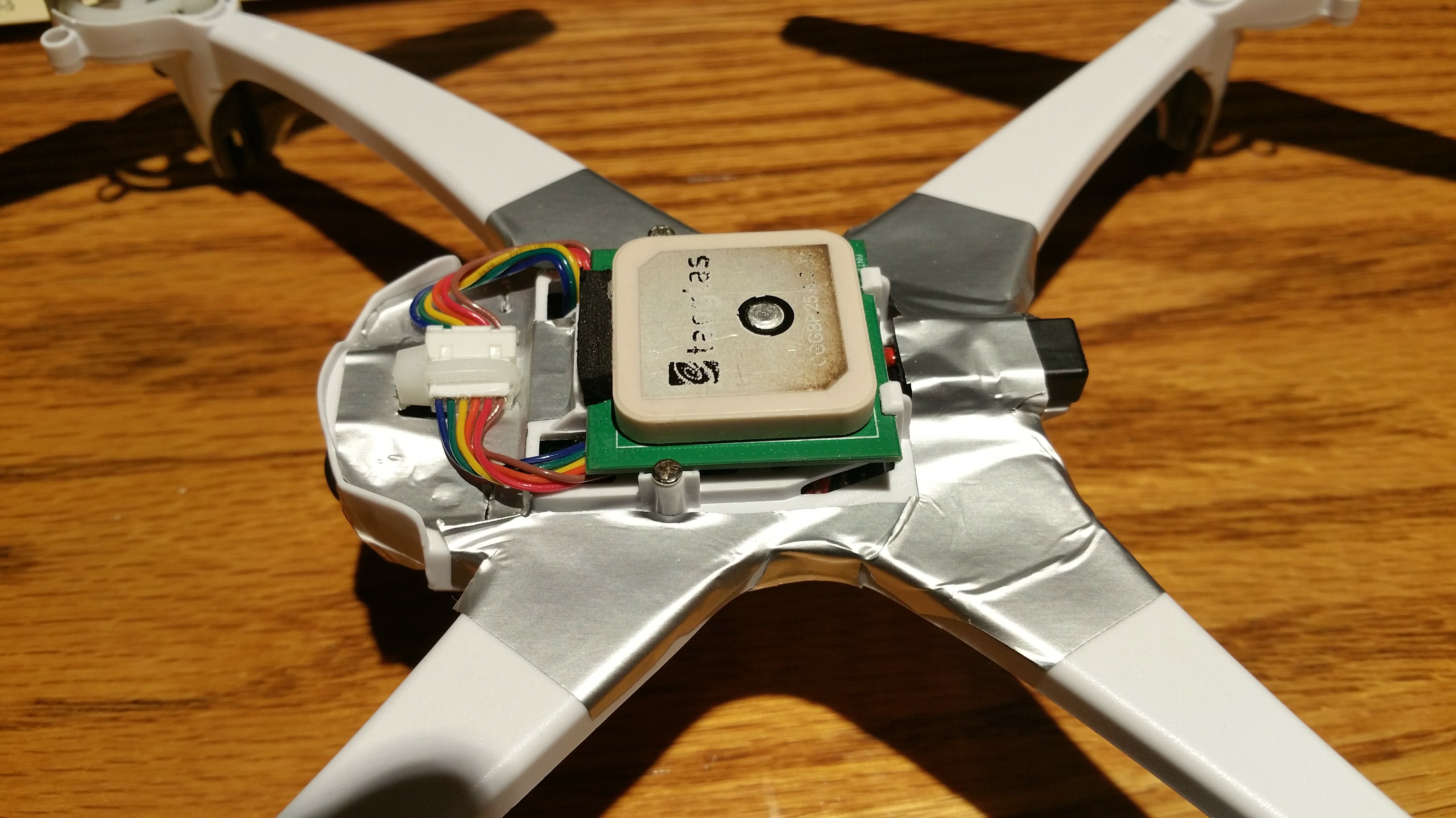
B. I added a layer of shield/RF absorbing tape between the GPS and the flight controller board. I purchased a sheet of 3M AB6005S EMI absorbing tape from Digi-key and cut a piece to fit the plastic layer between the flight controller and GPS. I cut a slot for the GPS cable and carefully applied it to the plastic on the flight controller side. The EMI absorber tape includes an insulator layer, but to be safe, I added extra kapton tape at points where the board might not be separated from the EMI tape by the pre-existing foam block. The EMI tape adds less than half a gram of weight. There is one potential problem with this modification. The tape blocks the holes in the plastic and will reduce air flow.
Hopefully the board won’t overheat. So far, so good, but it is winter here. I still need to check the board temperature after flying indoors.
C. While I had everything disassembled, I twisted the motor wires to reduce RF noise and magnetic interference. Be careful to route the motor wires in the narrow side channel to keep the antennas separated from the motor wires as much as possible when you reassemble the arms.
You will also want to perform both compass and motor calibration via the web page after reassembly since the positions of the wires have changed and the magnetic field induced by motor current will be affected.
I’ve only flown twice since making these modifications, but both times, I got a green light in less than a minute, much faster than most of my previous flights. In addition the ground station reported 3D+DGPS 1-3 minutes into both flights and the GPS drift was minimal. More testing is needed and I can’t be sure which of the two modifications might have contributed the most or any improvement, but it looks promising so far.
If anyone else tries either of these modifications, please let us know if you see improved GPS performance.
I’ve flown several more times with these modifications and the GPS still seems to be performing much better than it did previously. I even get a fast fix inside some areas of the house.
Unfortunately, it does seem to overheat when flying indoors. There must be some protection built in because after flying for about 3 minutes, power is reduced and it ends up on the floor until it cools off. I haven’t checked the logs yet, but I’m sure it just overheated. I’ll try removing the tape from the air holes and see if there is still enough shield to help the GPS. Or perhaps just the twisted motor wires will help.
I took a look at the log graph from the indoor flight and it showed thrust for one of the motors was maxed out when it lost thrust. M4 started out around half scale, similar to the other outputs. It stayed that way for a couple of minutes, then gradually increased while the other outputs stayed about the same until it reached maximum. This is when the drone lost power. It looks like the driver which overheated just reduced it’s actual output until the controller could no longer compensate by increasing the commanded output power.
In any case, I am sure it was a case of overheating. I removed the EMI absorbing tape from the inside of the frame shell. With the shell holes uncovered again, flying indoors for 15 minutes straight showed no sign of the overheating problem.
Of course, the poor GPS performance also returned. Obtaining a GPS fix took longer on the next flight outside and worse, after the controller indicated a good fix and hovering in loiter for a minute, I had to switch to altitude hold mode because the drone kept taking off in one direction or another. The ground station display showed the reported location rapidly drifting well over a hundred feet from the actual location. Apparently just twisting the motor wires does not help GPS performance.
Back to the drawing board in the next post…
After attempting a few flights with the GPS back to it’s original poor performance, I decided to try the EMI absorbing tape again. This time I would place it above the frame shell. I thought I might replace the GPS board with a layer of cardboard and EMI absorbing tape then mount the GPS above that, leaving the frame shell holes open for ventilation. But this would be quite a small shield unless I made the cardboard square larger than the GPS board. Then I thought, perhaps the EMI absorbing material didn’t need to be all one piece. So my plan was a small square of it under the GPS board and more on the top of the frame shell just outside the vent holes.
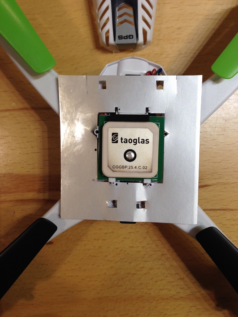
Attaching some tape directly to the top of the frame shell seemed easier to than figuring out how to place a layer under the GPS board, so I did it first. Here is a photo showing the EMI tape after being cut to the correct shape and applied to the frame shell. I cut out the EMI tape using a paper template I made with a square hole in the center about the size of the GPS board and shaped to fit the frame shell. This makes a funny shaped but continuous “ring” of EMI absorber which avoids covering the holes in the shell.
At this point I thought I might as well test to see if this part of my plan had any effect. I tested acquisition speed after powerup over a dozen times with the pictured simple configuration of EMI tape, both inside my house and outside in various locations. I have also flown a few missions with the EMI tape applied in this configuration. Surprisingly, GPS performance seems even better than previous experiment with the tape on the inside of the frame shell. I’m getting the green light on the controller very quickly, and the HDOP, GPS status and number of satellites all converge to favorable numbers in only a minute or two. I’m also not seeing any more of the wandering location issues after launch and I seem to be able to leave the SV in loiter mode for long periods of time without it wandering off as tries to compensate for the large GPS position errors.
I may never bother to add the square of cardboard and EMI tape under the GPS board as I had planned.
I’m honestly not sure why this is working so well. Perhaps most of the noise was coming from the video module and the ground plane inside the controller board was already blocking some of the RF noise near the center of the GPS module. Or perhaps the ring of shielding tape simply acts to increase the efective size of the ground-plane resulting in a stronger signal. In any case, I am much happier with the way it flys in loiter and auto modes!
Again, if anyone else tries this, please let us all know how it works for you.
(deleted post… I tried a mod that appeared to work, however when I reverted the SkyViper to stock condition there was no improvement. Currently seeing lock on 17-18 sats in an almost-open area.)
I only average a couple more satellites with my latest mod than I did with stock. But I do notice the faster lock, and most important, I haven’t experienced any of the large errors in reported position after getting a good lock. Also, you have to run a lot of tests to really be sure since GPS performance is impacted by weather, sunspot activity, satellite position, etc. I went through my logs before and after (about 70 flights stock and 30 tests with the mod), and the average improvement seems significant. Also, RF shielding can be a very finicky and non-intuitive thing, specially at high frequencies.
I was prepared to be less-than-impressed by my next test, this time with a carefully cut rectangle of 3M AB6005S sheet (backing material left attached).
However the time to lock was very fast, increasing quickly to 17 sats. Sending it up just above our roof line, the sat count went to a solid 19 for a couple of minutes, with little discernible drift in position. That said, there was only a 1 knot wind. 33 degrees F. During this flight, UAV Forecast was predicting 18 sats with a Kp of 1. Based on this non-rigorous test, this mod appears to be an improvement, although proof would require testing with two SkyVipers, one with the mod, one without.
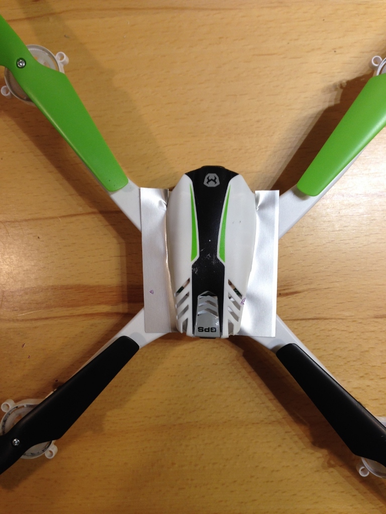
Adds about 2 grams, and will have some impact on its aerodynamic characteristics. Maybe a stamped version of the shield (or just an antenna ground plane?) will be offered for those DIYers who enjoy working with tiny screws. Images below.
It flies good enough for my purposes. It is possible that reducing the sheet size by trimming along the arms would reduce signal reception capability. It is also possible that vibration of the sheet could impede signal reception quality. I just went with the assumption that this was the largest, square shape that would not be affected by prop wash.
Hi Guys , i was trying as well to improve the gps as much as possible , i tried taking off the case and putting some absorbing tape too . will it be possible to put other improved gps chip on the skyviper , if so which ones will be best and compatible chips, do you think it will improve much ?