It can be used but all the inside walls would need to be made… so I say 50% usable.
Its the main body I am having issues. Figured if I could find some starting point maybe.
There is lots I can do in 3D but organic shapes I am struggling with.
Pm me on Facebook…
I’m curious about the drawings and want to try it. Can you share the drawings?
What drawings are you after
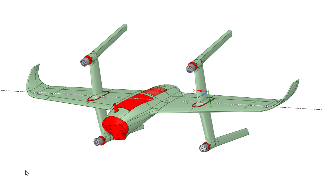
Hi all, I’m building a DIY tailsitter based on Fiitetest goblin but I got troubles that not smooth transitioning. I need help.
In that flight, the aircraft rolled naturally after transitioning from vertical mode to horizontal mode, but the response of the counter roll action to control it was poor. I felt that stick control was not effective. I then switched to QSTAB to prevent crashing to the ground, but the plane went straight to the ground (“Roll Error” occurred in that case). If this is the case, how should I change my settings?
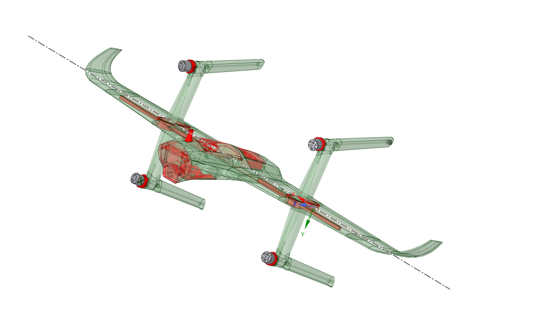
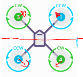
I am also concerned that this may be due to the layout of the motors in this aircraft (see photo) and the settings.
I have pasted a link to the parameters and logs for your reference.
Log:
https://1drv.ms/u/s!AptQrGcuGTl9hNtXAkeBjslQclUI5w?e=luMfEu
Parameter:
https://1drv.ms/u/s!AptQrGcuGTl9hNtjgbYqibLhsICBbw?e=eRAutB
[photos]

Before you stat transitioning you need to do some work on hover.
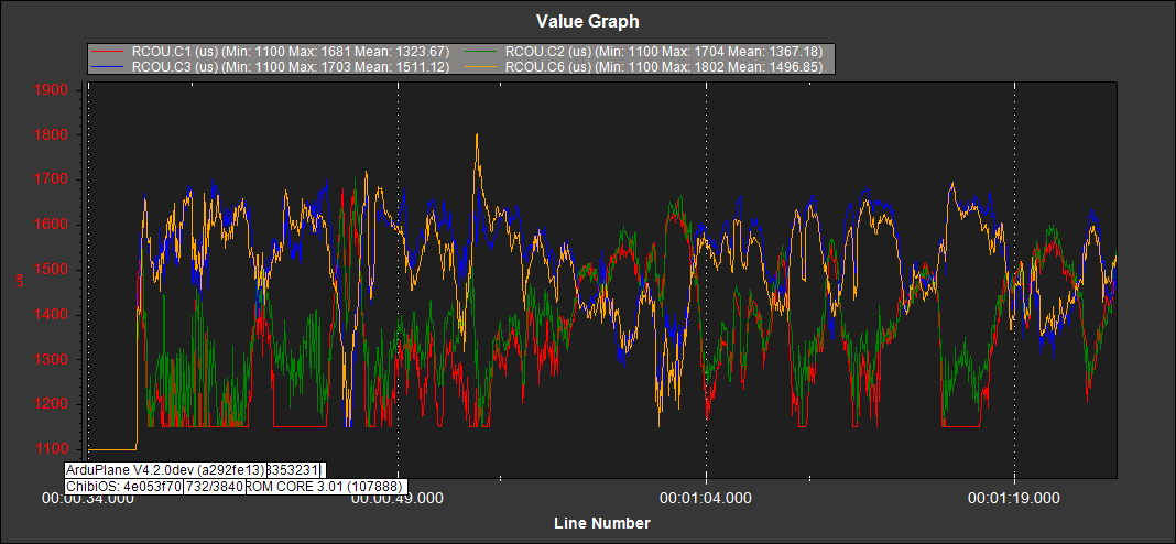
There is a very large motor imbalance. This is due to yaw in the copter view, the same as roll in plane view.
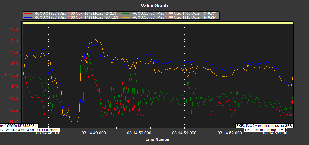
With such a big imbalance it is no wonder it was struggling in forward flight. The best way to solve is probably to setup eleveons. I see you have two output assigned to pass-through, if these are eleveons you should let AP control them.
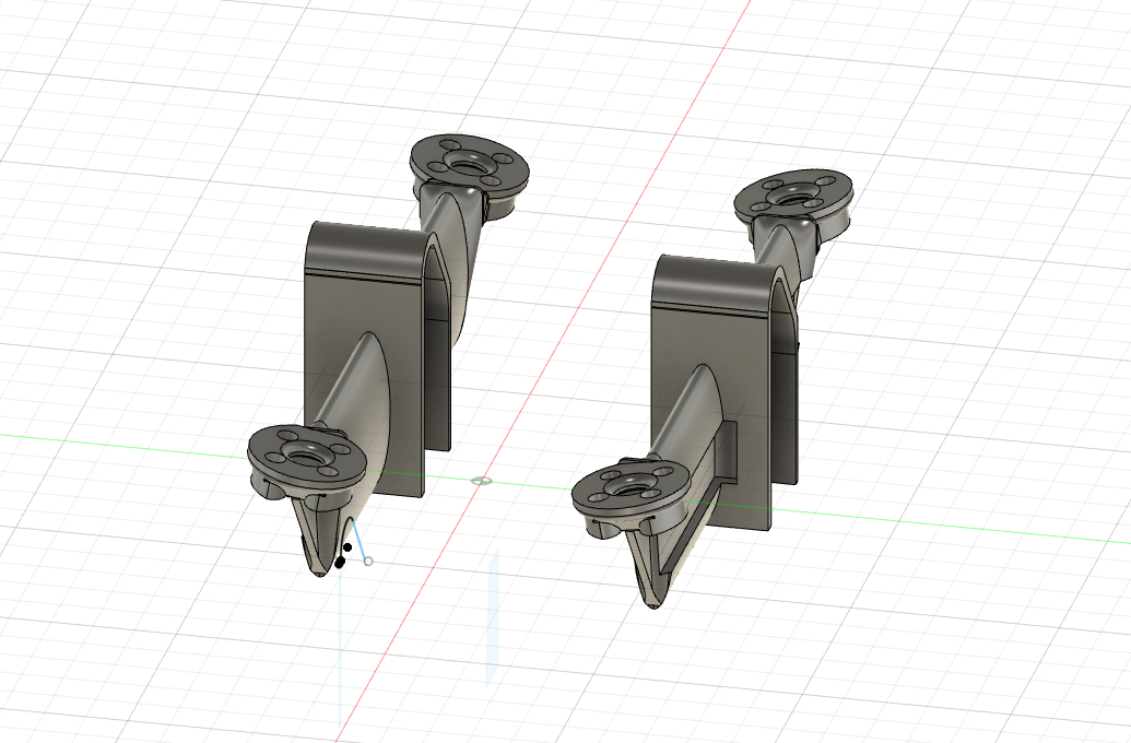
If you have no control surfaces you will probably have to mount the motors a 5 or 10 deg angle to get back some control authority. Just like the Foxtech H wing.
All motors should be within 100 to 200 PWM in the hover, the closer the better.
Thank you for your comment, I’m building this aircraft as a no control surfaces VTOL.
I saw the picture of the H-wing. As you point out, it is viewed from the top in airplane mode, the motors are mounted a bit towards the outside. Why does it need to be this way? Also, do they need to be tilted vertically (in the side view of the vehicle) like this sketch?


The tilt is such that the thrust of the motor acts in the same direction as the torque. CW motors must spin up to move the vehicle CCW, the motor mount vectors the thrust slight to help. Ideally they would be mounted so they are angled over relative to the CG. Think of a traditional X copter with tubular arms, you would just twist the motor mount on the arms slightly.
1 Like
H wing. my friend.This vehicle intrigues me.I want to produce a modified H wing.It has high maneuverability.Fast and agile like a racing drone.
I’m wondering about the engine pain too. Some forms are vehicles made with a 10’ angle. I am also looking for this tool angle value. Notify me.
The angle is to provide better yaw and pitch command.
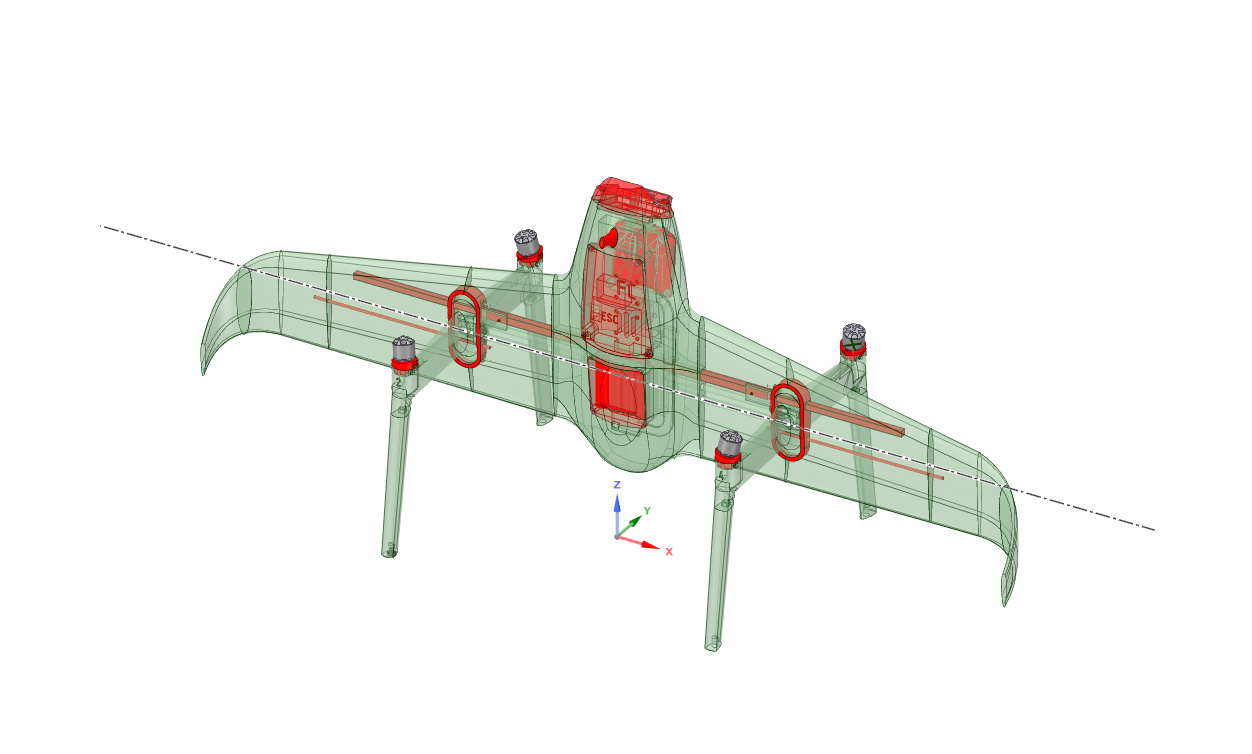
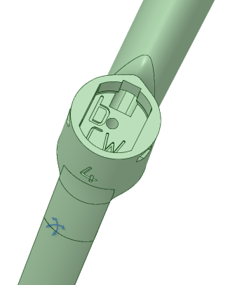
I have the H Wing clone nearly done from a drawing point of view. It’s never been printed nor assembled.
So long way to go still.
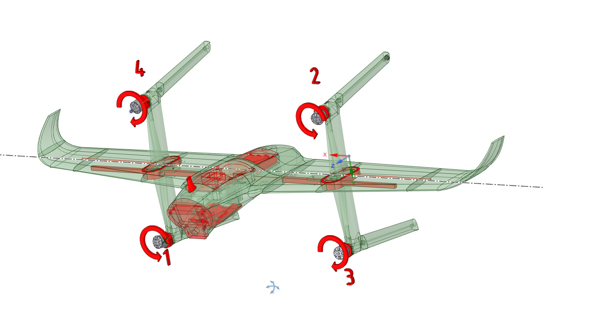
Each motor location is marked with direction, prop nut color and motor number.
1 Like
Thank you, I have the same problem
Thanks iampete and kadir_baydemir,
I’ve changed the angle of the motor bases to 10 degrees. Then I will adjust the output balance of the motor after replace to them.

After I replaced the motor holders, I did a quick hovering test in QSTAB mode. The vehicle is in the wind, but I have it under control.(In the previous version, I didn’t pay attention to the yaw axis controllability (it crashed immediately), so it’s hard to compare) I don’t know if the Yaw axis control has improved. The vehicle seems to be slower to respond compared to the racing drone, and also seems to behave differently than I intended with the yaw stick movement.
And I would like to know about the power balance of the motors, whether the current state is acceptable or not.
Thanks.

https://1drv.ms/u/s!AptQrGcuGTl9hNxbWayFkQZwZCfyXA?e=gbdGmj
Its still struggling. I think its just a factor of small motors and a big wing. I think it is better than it was.
This is the split.
Q_M_SPIN_MAX to 1 and Q_M_SPIN_MIN as low as you can should help.
1 Like
You’d get more yaw torque from motor tilt if the motors were further outboard and tilted toward/away from the wing.
1 Like
I think the response of the yaw axis has improved. Also, the motor output balance seemed to be stable since it was a light wind that day, is this condition appropriate? If ok, I would like to do a transition test next. Appreciate your advice.

Its certainly better. But more yaw authority is always better. As Mark says you could tilt more. Currently you have the motors tilted forward and back this:

For maximum effectiveness you should tilt on a axis that runs through the CG.
You will have to excuse the bad paint skills. 
That it was a square that would get you 40% more yaw sqrt(1^2 + 1^2). Since your not square you should get even more.
1 Like
By “further outboard” I meant moving the motor mounts outward toward the wingtips, further from the CG, which will increase the moment arm for body-frame roll and yaw.
2 Likes