Control ws2812 matrix led with script lua on PIXHAWK 4 MINI

Hello everyone.
This is a post after this first one (you dont need to read it):

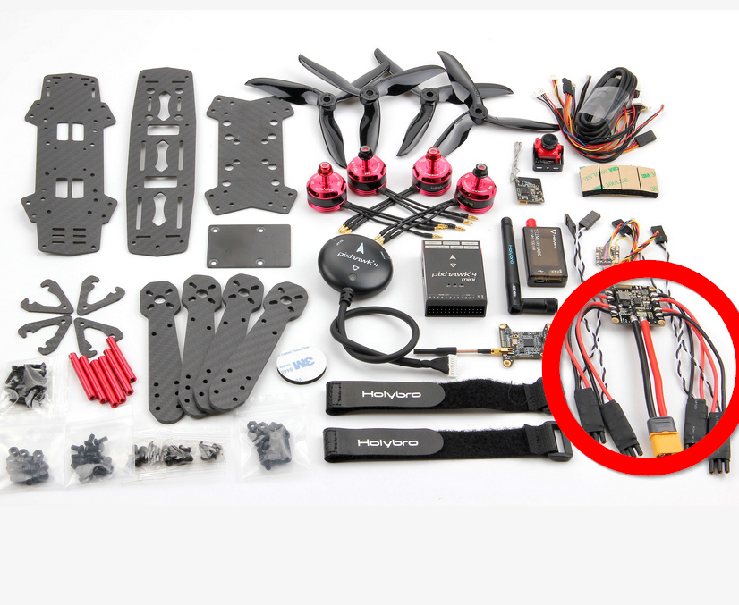
What I’m trying to do ?
Connect a WS2812 capable matrix led to my flight controler and manipulate it thanks to lua scripting provided with ArduPilot.

I’ve flashed my flght controler with ardupilot and perform all sensors checks, thanks to QGroundControl. My quad is almost ready to fly, I just want to add a matrix led on it and control it’s behaviour thanks to lua scripting.

After reading the documentation, I’ve understood that SERVOn_FUNCTION are parameters available to control the behaviour of SERVO outputs, wich makes possible to use extra ports unused for motors to control other output. Functions are listed on the documentation, and regarding lua scripts it looks like it should be set to 94. Because I’m trying to use my MAIN OUT 6, I’ve set my SERVO6_FUNCTION to 94 here


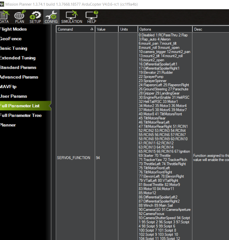
(I’ve already set SCR_ENABLE to 1)

Then I’ve put the following script inside my APM/scripts folder

The only modification I’ve made on the script is replacing “gcs:send_text(6” by “gcs:send_text(0” to make sure to see them inside “messages” panel on Mission Planer.

I’ve opened up my “messages” panel on Mission Planer and when I plug my quad with my liPo battery and then “connect” my Mission Planer to the drone port, I can see the debug line “LEDs: chan=6” Wich looks great for me ! It appears that the lua script I’ve found the correct MAIN OUT port where my matrix led is wired !

However, my matrix led kept light off :confused:

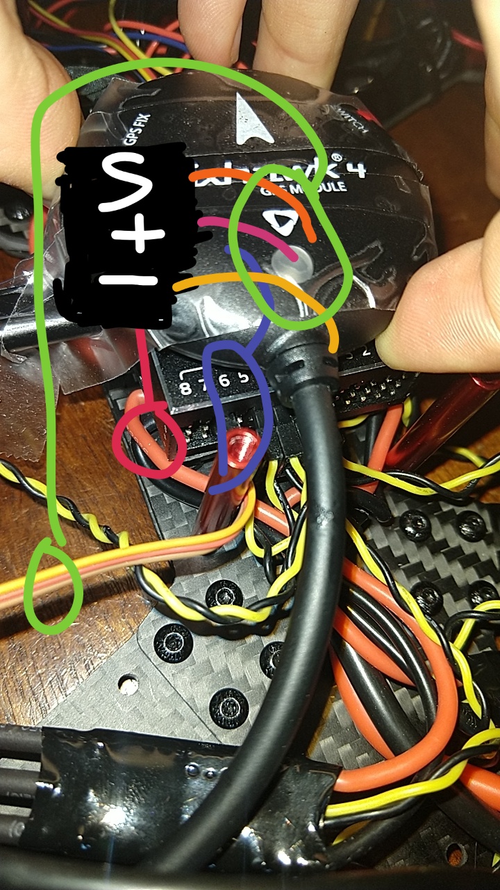
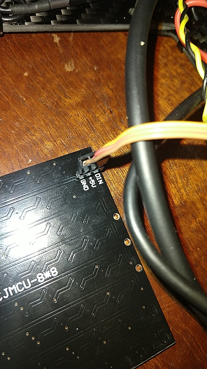
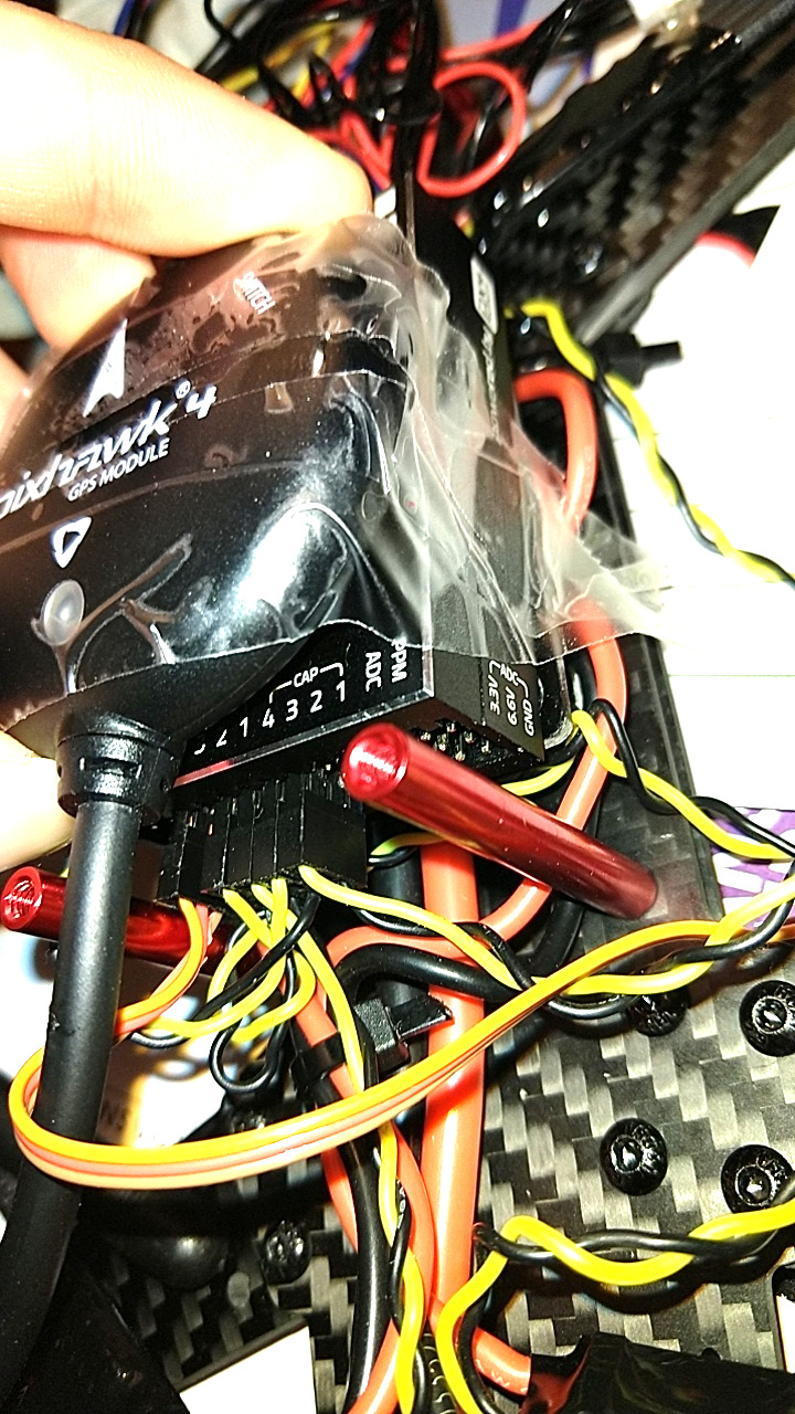
Here are more pictures about the wiring part

(on the Pixhawk MAIN OUT 6)

(to the Matrix Led ws2812 compatible)

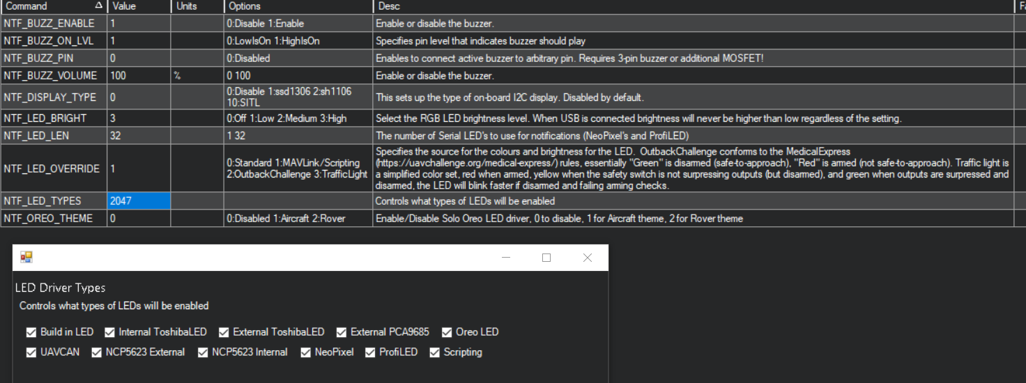
I’ve also set NTF_LED_TYPES like this:

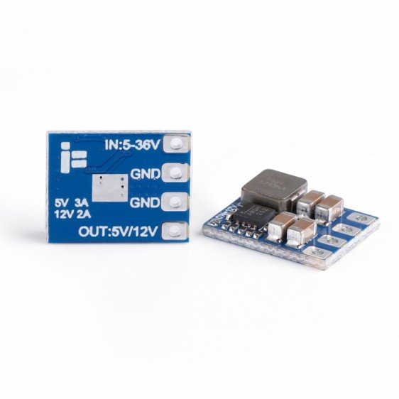
I don’t understand why the matrix led stays off. Should it powered from an other source ? I’ve also tried to set (temporarly) SERVO6_FUNCTION to 33 (motor 1) and have set SERVO1_FUNCTION to 0 (disable) and perform an arm action. The motors 2, 3, and 4 have spinned as expected, but I believed that it should powered on the WS2812 matrix but it didn’t !

I hope you can help me here and wich you a happy new year !

The servo rail isn’t powered by the flight controller - you need to add a BEC / 5V source to the rail.

Thank you for your answer,
i’ve checked ESC connections and I confirm that they are powered from the Power Board module here from the kit here:

I think that + and - signs are only usefull for input inside the flight controller and not for servo output right ?
However, I’ve found on the other side the flight controller the following mentions:


So I’ve plugged my matrix led on the PPM port (just for testing) and after a drone reboot with the battery, the first led of the matrix briefly powered on ! I’ve tried two or three times, sometimes it’s red, other time white, or blue. I believe the flight controller try to initialize the PPM communication and the ws2812 matrix led interpret (wrongly) some “radio signal” as a “light” message ? If yes, can the pins be stabilized to output 5V and control the matrix led without adding a BEC ?

If not, I’ve found the following BEC:

it interest me because it can output between 5v to 12v and between 2A to 4A wich is the maximum acceptable voltage (5v/4A) accepted by the matrix led from Amazon Documentation. The 12V is interesting if I want to change the matrix led for a bigger light in the future.

However, I am not understanding how I’m supposed to connect it to my XT60 input ? I’ve also found the following product:

is it somehow related ? May I safely split my 4s liPo battery xt60 input in two parts, one for the Power board module powering ESC + Fligh Controller and one other for the Matrix Led ?

If my previous suppositions are right, then I will need to wire the bec to my led matrix with the red and the black wires (5V powering) and one other wire from the PWM Output (6 for example) to control the matrix led behaviour right ?

Progress! Cool. A 5V Bec is my suggestion.

Ok, I think I’ll go with the following (tahnk you again for helping me).
I will connect my lipo battery to one of this xt60 splitter:
31Sj42BEWCL.AC_SY1000
Then I will plug my power board module on one of the splitter output.
On the other splitter output, I will connect a xt60 female wire and solder it on DCIN/GND on the following BEC

I will also solder two wires (male to male) on the output of the BEC directly to the + and - of the led matrix. Then I should plug a female to male wire from the signal MAIN OUT PWM 6th of pixhawk to the signal input of the led matrix and then everything should work properly ? or I’ve missed something :thinking: ?

Thank you again for your time, if you confirm my plan I will try with a raspberry pi (powered from the ground) just to ensure led matrix can be externally powered but controlled from flight controller !

I’d use signal and ground to the flight controller if you’re going to do it that way. But that wiring scheme should work.