Clearing up a few Questions

Hello Everyone.

Apart from my perpetual issues with the INS, I have a host of questions that I simply cannot find any information on. Sadly, despite my best efforts, I cannot find a decent source of information on the Pixhawk. There seem to be quite a few different resources available, some more complete than others, and some offer conflicting information. I really have tried to answer these questions myself but I cannot.

First off. Power.

Some sources state that the Pixhawk is “Servo rail high-power (7 V) and high-current ready”. Yet another states, “The power module is NOT suitable for powering servos. It is solely intended for the autopilot - so the system needs an additional BEC or an ESC with integrated BEC.”

What is the story here then? If it makes any difference, I am speaking in particular with regards to fixed wings…

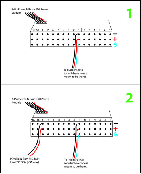
If I plug my battery into the 3DR power module and plug the six pin connector into the Pixhawk power port on the top, will I then be able to plug my little 9g servos directly by plugging them into the servo rail? IE, the rudder servo can plug right into the +, - and signal pins and be powered just fine?

Or do I need to supply power from my ESC (which has a 5.5v BEC) to my servo rail by simply plugging + and - from the BEC into any available + and - RC input?

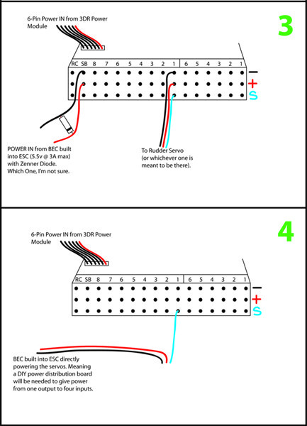
If the second option is required, am I correct in assuming that a Zenner diode will be needed to protect the servo rail from voltage spikes?

Next up is some more power questions…

The AUX outputs and their power needs…

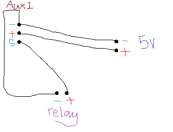
To operate a relay or a LED or anything using the DO_DIGICAM_CONTROL, with the servo option, additional power needs to be supplied to the AUX rail by proving 5v to any of the available + and - AUX pins not in use, correct?

I’ve done this but the output isn’t enough to trigger even a 3.3v relay and only barely lights up an LED. I have not tested the output values with a multimeter. This is how I’ve wired it as per the instructions from 3DR:

Where am I going wrong?

Next up is a basic question I simply need some confirmation on…

During the compass calibration, should one point the axis magnetic North? It is magnetic North, right? Not due North?

On the compass again, I get told I should get “133 90” samples. That is a pretty unrealistic number, what is the real world optimum?

Thank you, folks. Any help will be much appreciated and dutifully paid forward.

KD.

I should add that the diode I have, and the one closest to what I think is the same spec as the recommended part is a PE4148 and I have no idea if it is suitable… I cannot find the same part as that listed. I am not keen on testing any of the power issues out myself until I can clarify my questions or at the very least find the correct diode to protect my Pixhawk from spikes.

Hi Folks. So I still can’t find solid info on this problem, specifically the power.

Here are some example diagrams. Could someone please tell me which one is going to work.


The last option seems like a lot of extra wiring to me. Additionally, the BEC output from the ESC actually has 3 wires. What the third wire is I have no idea.

KD.

To aid anyone who might happen upon this wondering the same thing, I have been told by Santiago from 3DR support (via email) that options, 2, 3 and 4 are all viable.

The diode technically should not be required when using the output from the ESC’s BEC because it is meant to prevent voltage spikes itself anyway. However, it would be good practice to utilise the diode as one never knows the quality of the ESC and just how well it will prevent voltage spikes. Besides, spending a few cents on a diode versus spending a lot more on a blown Pixhawk seems like a no-brainer.

I will update with any new information I get.

Hi kdstanhope,

For option 4 you also need to connect the ground to the Pixhawk, not only the servo signal wire.

More information here:
pixhawk.org/users/actuators/pwm_escs_and_servos

Apart from RogelioN’s input, this topic seems deader than disco… @RogelioN, Thank you by the way!

So the fourth option required the ground lead into the Pixhawk as well, apart from that it is a viable option, albeit a slightly impractical one for general use. I do imagine that some may find this option useful in certain situations so it should not be dismissed.

To clarify again:

Options 2, 3 and 4 are all viable.
When using a BEC to power the servo, the power source is meant to be regulated in the first place so a Zenner diode is not required, but it is a good idea to use one nonetheless.
Option 3 is the recommended.

Aux output rail and main output rail share Vcc and ground so once you power the servo rail as per options 2 or 3, you should get sufficient power output on the AUX rail to power a LED or a relay up to ~5v.

KD.

THANK YOU!

This is exactly the same question I had.

So for option #2, the power that comes from the BEC that powers the rails, can I run that from the power block that come with the pixhawk too? Or do I need to buy another battery and another BEC?

I also found this picture

Source: copter.ardupilot.com/wiki/advanc … ing-chart/