I am trying to connect trough wifi, the video transmission works with the link posted previously. The Mavlink does not, but I hope, that with your findings and settings we can find the solution.
I’m not incredibly optimistic about Mavlink access via Wi-Fi – my test results are like other folks – video only. The “standard” ports do not seem to behave in “standard ways” or simply are not present. There are other ports open whose behavior is unknown. We shall see. However, it appears that wired connections will do fine. Just determined that while the unit normally powers down automatically after something like 7 minutes of idle, when connected by USB to a PC it doesn’t self-power down. You can do most Mavlink functions with the unit turned off and no battery, but for some Mavlink functions the battery needs to be in and the unit fully powered on. By the way, the base version of the (presumably heavily modified) ArduCopter firmware appears to be 3.4.0dev.
Of course it may be technically possible to change parameters on the PX4 to enable Wi-Fi Mavlink access (though care would need to be taken to avoid messing up the unit’s core functionality, remote relay functions, etc.) But I’m not optimistic that this kind of Wi-Fi access is possible without first having the USB wired access to change those parameters. Again though, it’s really too early to know.
What I made so far, is to install a packet capture software on my android phone and listen to the conversation with the C-Fly app. It was easy to identify the video link rtsp on tcp port 19200.
1.) On udp port 10005, I was able to read a message which contained words like “FS_BATT_VOLTAGE” and “TWO_BATT_VOLTAGE”.
2.) On tcp port 4646 from the drone: { “CMD”: 0, “PARAM”: { “FirmWare”: “vA.7.19101201”, “platform”: “A7-4K-1463-2-16-1-2-00100009-1-101-1-18-106-1-2-1”, “pinp_X”: 60, “pinp_Y”: 6, “region”: -1, “cur_csi”: 0, “card_status”: 0, “freeSpace”: 0, “usedSpace”: 0, “totalSpace”: 0, “ssid”: “Drone-9a1327”, “band_status”: 0, “band_ip”: “NULL” }, “RESULT”: 0 }
3.) On tcp port 10002 and 10003 seems to be an TLS encrypted communication, but I am not sure.
What did you configure on MP and QG to communicate trough the USB port?
On Linux it’s a normal /dev/ttyACM0 port, and MP connects at the usual 115200. QGC connects automatically to that same port on startup. A few notes:
I haven’t checked yet to see if it’s possible to create DATAFLASH logs.
If a battery is installed when the USB is plugged in, the unit will power itself on automatically. If no battery is installed, there is still access to the PX4 in a typical matter. As I mentioned, when USB is plugged in and connected to MP, etc., the unit no longer automatically powers off after 6-7 minutes.
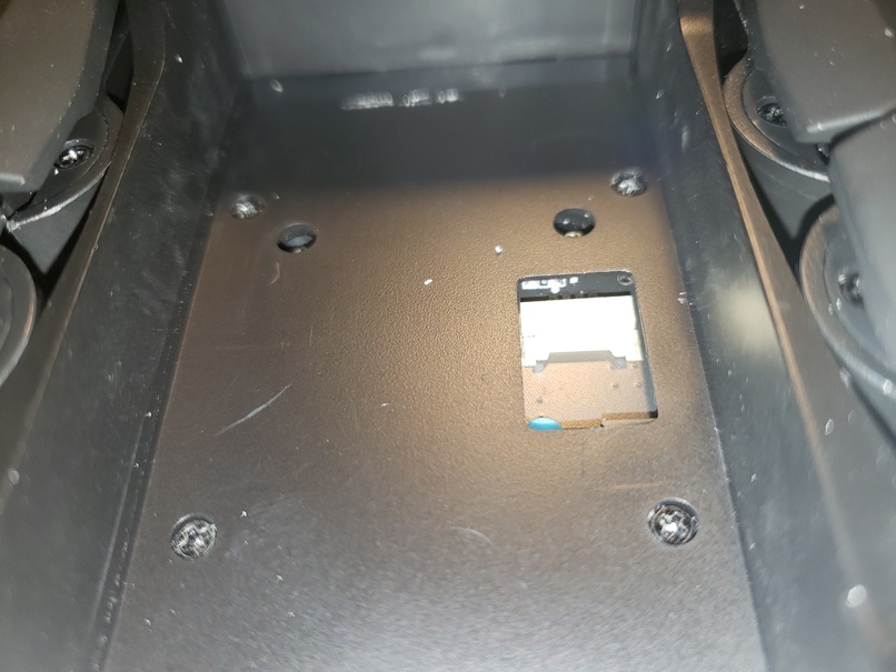
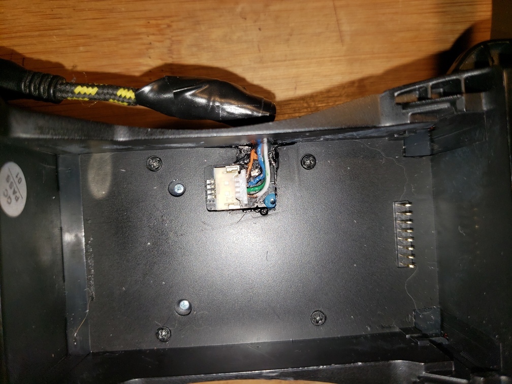
The Molex connector (which is under the label at the bottom of the battery compartment) is extremely small, low profile, and fragile. It’s a female housing with four tiny male pins. Molex considers this part to be obsolete, and while some sources will still claim to carry it and the matching male housing and pins, in practice it’s out of stock for most. It is not practical to repeatedly insert and remove the matching part without risking destroying the side attached to the PC board. The part is really designed for a “permanent” internal connection where it would typically only be plugged in once and left plugged in. There is also literally no room to install another connector inside that battery compartment, the tolerances are very tight. In fact, even extremely thin wires I used for initial testing made it difficult to insert and remove the battery and those wires could only be used once due to damage from the battery housing. The male housing pins themselves are also extremely tiny, and very fragile even when crimped correctly. I finally gave up on using them, and as you’ll see when I upload photos, chose to use thin solid conductor wires inserted directly through the male housing to contact the pins on the female side. Then the four conductors are brought directly out the side of the unit via a tiny channel that I cut and an appropriate hole. There turns out to be just barely enough room down there to do this without interfering with the battery. The conductors are held in place in that location using some CA glue.
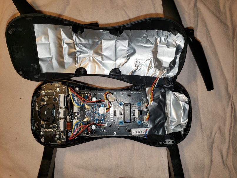
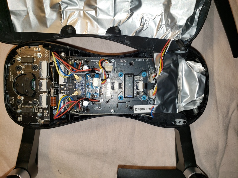

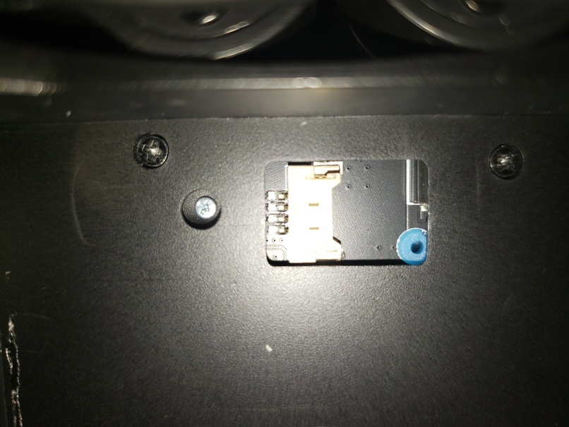
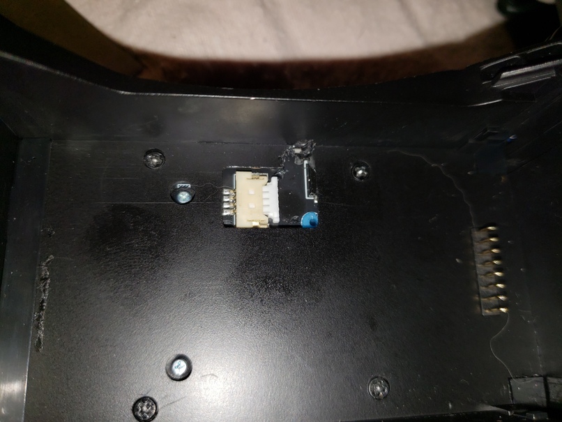
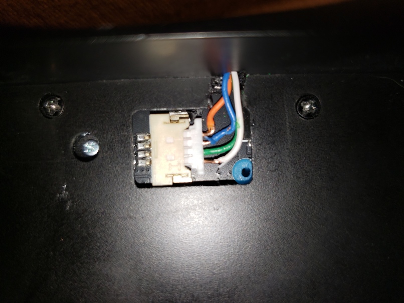

Viewing the connector with the open end on the right as in the above photo, the signals are:
----- +5
----- DATA+
----- DATA-
----- GND
The connector you need to mate with the connector in the unit is designated: MOLEX 0511460400. As I mentioned this typically comes without the crimp pins (though there are exceptions to this). The crimp pins for this connector are designated: MOLEX 0506418141. However, also as mentioned above, I ultimately decided not to use them due to their fragility.
If you want to avoid obtaining the mating connector, an alternative would be to connect to the four solder points just to the left of the connector installed on the board. However, I did not consider this to be an appealing prospect for a variety of fairly obvious reasons.
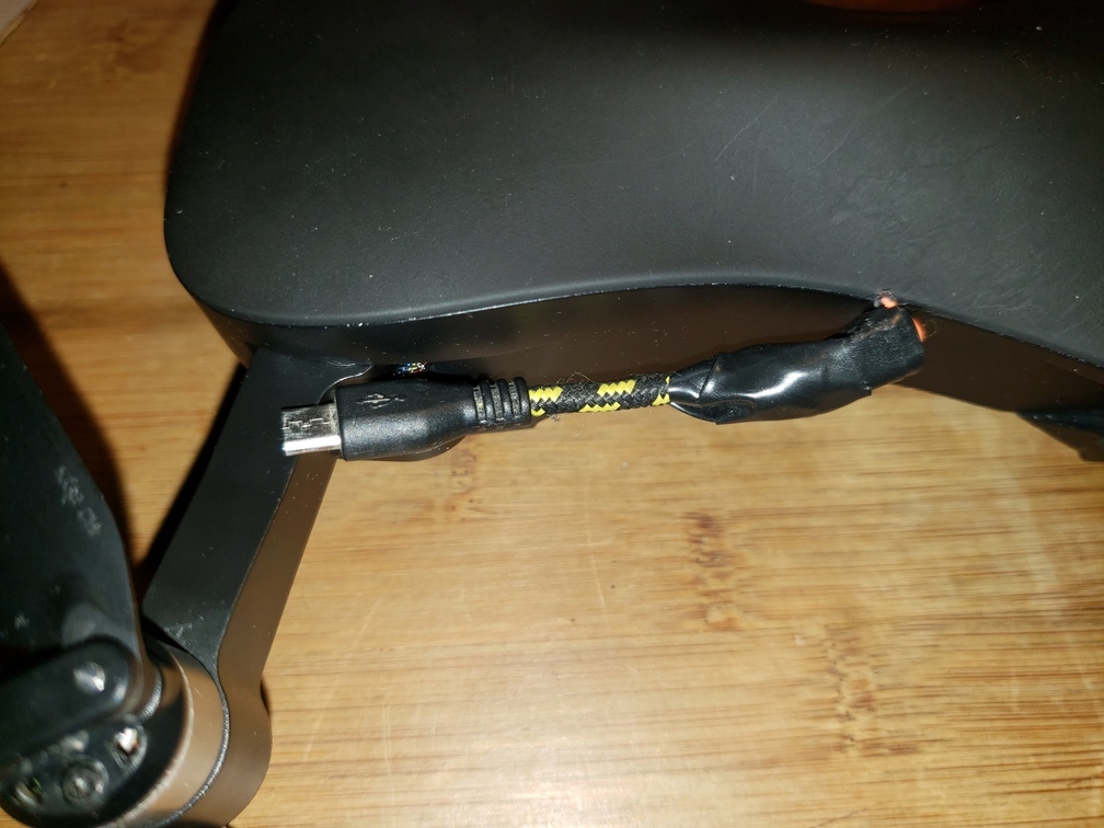
And here’s how the external USB connector is set up for now. Yeah, I know it’s not pretty, but it’s functional, and doesn’t interfere with operations. Weight is only a few grams.
Hi there i’m so happy to see these everything hardware things i have done with my JJRC X9 new motherboard but i was able to make it function only with the X9P firmeware coz thats the only one available in thenet. Im using the usb DFU and STlink for programming. Please share your firmware. Mine is / new board (FLIGHT-DF801-v3.9-2018.11.26�Boot-Dream-v%d.%d.%d�FLIGHT-DF801-v3.9-2018.11.26 (36ea946c)�PX4: c4dfb9bf NuttX: 258f2257�Frame: QUAD) https://www.mediafire.com/file/jr18jratec1lavi/RD_FR_STLINK_X1000000.bin/file https://www.mediafire.com/file/mggr4nwvadqbnnl/x12_2_full.param/file
Hope we can break this thing. Also this https://www.mediafire.com/file/lt0djc7ltt0v2o4/CFLY-UPDATE.zip/file helps me whenever i messed up big time it will restore RC control, etc.
I’m not altering the firmware at this time. It’s obviously a custom build and I don’t want to damage existing functionality. My primary interest has been the ability to alter ArduCopter parameters, etc. via Mission Planner/QGC.
Yes we are not doing that of course if we can be able to backup firmware it would be a good practice since it’s prone to be corrupted and there is no support we are all alone. Thanks!
Hi all does anyone able to backup there firmware already? I’m stocked to X9 which have entirely different hardwares. Please if any one can share’ thank you so much!
Good morning, the firmware that you put here is valid for the Eachine ex4? and my question if it is worth what improvements do you have? I contacted the C-fly company to find out if there is firmware for improvements and no one answers … everything happens
1 Like
It’s for JJRC X12 a new board but not compatible with my drone I need another firmware to work with my existed parts like camera gimbals. I succesfully make it work by flashing fw_JJRC_X9P-v2.3_rev but downgraded to X9 which don’t have the sam gimbals and other things also it’s parameters. It work but can’t fly somethinf to do with it’s parameters, propellers not stabilized for X12. Hope one day some one can share their X12 firmwares.
There may be some duplicate information there since you can connect from the C-FLY app either to the drone wifi or to the controller wifi so there may be different ports for how you connect, either directly to the drone or via the wifi repeater from the controller.
As far as I know MAVLink aren’t encrypted so there must be something custom or something else not related to the MAVLink comms.
Did anyone take a look at the Listener logs created by the C-FLY app? These seem to be a reduces text version of the tlog telemetry files produced by regular ArduCopter+MAVLink+Mission Planner.
From looking at the extend of mods required to get a USB connector to the drone I honestly don’t think it’s worth the trouble since the only parameter I’d change is the RTL_ALT from 30 meters to 0 (i.e. keep the current altitude) and maybe some of the other failsafe like geo-fence geometry.
1 Like
Once the USB is accessible, a Raspberry Pi Zero W becomes an excellent companion computer. This means the full range of functionality, including proper mission planning and saving (by itself, the drone will not save any missions), full telemetry logs (also not saved by the drone), and both Wi-Fi and telemetry radio connectivity (e.g. 915 Mhz). And of course full parameters and operational controls from QGC, Mission Planner, etc. The Pi can be powered from the drone itself.
1 Like
Absolutely, access to the USB port enables full control over the board but it does carry over the risk of damaging the board while mounting the USB plug adapter. For those with precise fingers, the right tools this might not be a big deal but for the majority of owners of the X12/EX4 the skill to mount the MOLEX plug with its wires in place then securing the USB socket on the outside of the body without compromising the battery compartment’s proper tight fit may not be so easy to do. Particularly when the thing you’re after isn’t to experiment with the X12’s ArduCopter settings or firmware, although I do get an itch thinking about it 
Since I saw the app is putting out what looks like stripped down MAVLink output I’ll see if the wifi connectivity to the drone doesn’t already allow that. After all the telemetry data and all the other MAVLink info that gets displayed and the settings as well are sent via the wifi so I’ll see if any of the ports that the drone listens to are accepting or putting out Mission Planner or MAVLink data. Maybe we get lucky and won’t have to drill holes in the body of the quad.
Still from an experimental point of view having the USB plug is definitely a must.
1 Like