I’ve just replaced a pixhawk 1 with a Durandal. Pretty much all the parts are original 3DR ones. I had to rewire and re-crimp everything as the Durandal has this multipurpose GPS connector that includes the buzzer safety switch. Everything works apart from the buzzer. I’m pretty sure I have it all wired correctly, just wondering if anyone else has had success with a non-Holybro buzzer and the Durandal?
Holybro’s GPS/mag/safety/buzzer piece of chinese engineering contains a magnetic buzzer, not a piezo one. It’s not like it’s going to beep very much, but still… packing together worst GNSS antenna choice with the mag and a magnetic beeper !? C’mon…
I haven’t bothered with the switch and the buzzer on the Pixhawk4, but I’ll give it a shot tomorrow. I think they may be driven differently.
I have managed to drive a buzzer through AUX5 by making the following change to hwdef.bat:
diff --git a/libraries/AP_HAL_ChibiOS/hwdef/Durandal/hwdef.dat b/libraries/AP_HAL_ChibiOS/hwdef/Durandal/hwdef.dat
index e2c696622c..233eb9f21b 100644
--- a/libraries/AP_HAL_ChibiOS/hwdef/Durandal/hwdef.dat
+++ b/libraries/AP_HAL_ChibiOS/hwdef/Durandal/hwdef.dat
@@ -182,17 +182,17 @@ PE14 TIM1_CH4 TIM1 PWM(1) GPIO(50)
 PA10 TIM1_CH3 TIM1 PWM(2) GPIO(51)
 PE11 TIM1_CH2 TIM1 PWM(3) GPIO(52)
 PE9  TIM1_CH1 TIM1 PWM(4) GPIO(53)
-PD13 TIM4_CH2 TIM4 PWM(5) GPIO(54)
+PD13 TIM4_CH2 TIM4 PWM(5) GPIO(54) ALARM
 PD14 TIM4_CH3 TIM4 PWM(6) GPIO(55)
 # we need to disable DMA on the last 2 FMU channels
 # as timer 12 doesn't have a TIMn_UP DMA option
 PH6  TIM12_CH1 TIM12 PWM(7) GPIO(56) NODMA
 PH9  TIM12_CH2 TIM12 PWM(8) GPIO(57) NODMA

-define BOARD_PWM_COUNT_DEFAULT 8
+define BOARD_PWM_COUNT_DEFAULT 4

 # PWM output for buzzer
-PE5 TIM15_CH1 TIM15 GPIO(77) ALARM
+#PE5 TIM15_CH1 TIM15 GPIO(77) ALARM

 # analog in
 PA0 BATT_VOLTAGE_SENS ADC1 SCALE(1)
It’s a little quiet as it’s 3.3v but better than silence. Still no joy driving the buzzer through the actual buzzer pins…
EDIT: don’t try this at home! Apparently anything more that 20mA will overload the GPIO pins
1 Like
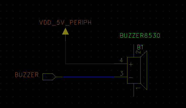
I have resolved this - the issue is really in the pin naming. The correct connections are:
Buzzer- goes to Pin 9 in the GPS header which is labelled "Buzzer +5v"
Buzzer+ goes to Pin 1 in the GPS header which is labelled "+5v"
According to Holybro an additional resistor of 10ohm in series is required to limit current draw and prevent the 5v supply being unusable for peripherals. There is however 1.5A over current protection in the buzzer pin so no danger of actually damaging the board. The buzzer sounds nice and loud with these connections.
2 Likes
Great stuff. I brought this up on the dev call this morning as one of the outstanding Copter-4.0.0 issues (can’t remember if you were there or not)… but seems like you’ve got it all under control which is great, thanks!
Yeah - I got an update from Holybro, they recommend a 10ohm resistor in series to make sure the supply voltage can always feed the peripherals.
One final note - the original 3DR piezo buzzer does not work, it is rated much higher than 5v and you cannot hear anything if you use it
1 Like
The piezo will need an external driver chip to boost the signal to 25~30V. All those buzzer driver is designed not very well, there is no flyback diode which can cause a very big voltage spike, up to 20V that can damage the other components