Beaglebone Blue + Airspeed Sensor via ADC

Hello everyone,

I think I’ve run out of stamina on the search for the answer. I’m so close, but I just can’t make the connection.

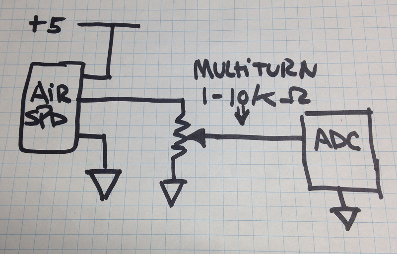
I’m trying to make use of the CJMCU-36 analog airspeed sensor with Ardupilot:Plane on the Beaglebone blue.

This sensor offers an analog reading of .5v to 4.5v, which is way higher than the 1.8v maximum permitted by the ADC on the beaglebone (citation here in lower right corner of bullets regarding connections):

Easy connect JST interfaces for adding additional buses and peripherals including: GPS, DSM2 radio, UARTs, SPI, I2C, 1.8V analog, 3.3V GPIOs

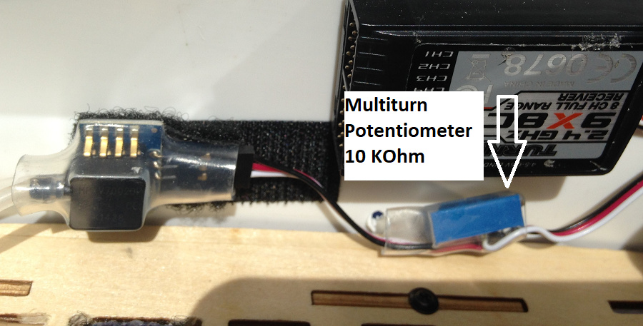
I added a 1.5kOhm resistor on the analog signal line between the sensor and the board, and a 1kOhm resistor between the sensor and the board’s ground to reduce the analog output voltage to a max of 1.8v. I used this calculator to figure that out.

I’ve managed to figure out the device name of the ADC in the beaglebone and determine which pin is which:

Physical connection from Numo Silva’s graphic found near the top of this thread:
https://groups.google.com/forum/#!category-topic/beagleboard/ZXSTPIcV4OU

sysfs location of adc inputs
Info on how to find ADC device in linux sysfs

debian@beaglebone:~$ cd /sys/bus/iio/devices/iio\:
debian@beaglebone:/sys/bus/iio/devices/iio:device0$ ll
total 0
drwxr-xr-x 2 root root 0 Jun 1 20:46 buffer
-r--r--r-- 1 root root 4.0K Jun 1 20:46 dev
-rw-r--r-- 1 root root 4.0K Jun 1 20:34 in_voltage0_raw
-rw-r--r-- 1 root root 4.0K Jun 1 20:34 in_voltage1_raw
-rw-r--r-- 1 root root 4.0K Jun 1 20:34 in_voltage2_raw
-rw-r--r-- 1 root root 4.0K Jun 1 20:34 in_voltage3_raw
-rw-r--r-- 1 root root 4.0K Jun 1 20:34 in_voltage4_raw
-rw-r--r-- 1 root root 4.0K Jun 1 20:34 in_voltage5_raw
-rw-r--r-- 1 root root 4.0K Jun 1 20:34 in_voltage6_raw
-rw-r--r-- 1 root root 4.0K Jun 1 20:34 in_voltage7_raw
-r--r--r-- 1 root root 4.0K Jun 1 20:46 name
lrwxrwxrwx 1 root root 0 Jun 1 20:46 of_node -> ../../../../../../firmware/devicetree/base/ocp/tscadc@44e0d000/adc
drwxr-xr-x 2 root root 0 Jun 1 20:46 power
drwxr-xr-x 2 root root 0 Jun 1 20:46 scan_elements
lrwxrwxrwx 1 root root 0 Dec 31 1999 subsystem -> ../../../../../../bus/iio
-rw-r--r-- 1 root root 4.0K Dec 31 1999 uevent

The software path in linux to see raw values of the ADC shows that values are changing when I blow on the pitot tube (though more than 1 are changing, which seems unusual to me…)

while true; do cat in_voltage* | paste - - - - - - - - ; sleep 1; done
4074    3807    3940    2284    2596    2830    1665    3810
3148    3611    3953    2210    2727    2832    1718    3811
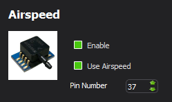
Configuring APM
APM Planner 2 provides a pin selection field and ranges fro 0 - 100:
image

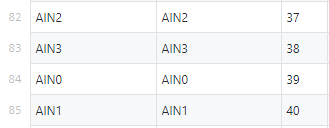
This pinout table on the beaglebone github page seems to indicate the ADC pins range between 37-40.

image

Yet none of these pins results in a change of value on the HUD airspeed indicator.

So that’s where I’m stuck. I have analog voltage within spec entering the board and responding to polling, but I haven’t figured out how to tell APM about it.

Does anyone know what I’m missing here?

Thank you!

Hello,

What ArduPlane version are you running ?
Looking at Master,it seems that all is there and well defined.

And reads the correct source

Please note that in_voltage0_raw is dedicated to Voltage Sensor & in_voltage1_raw to Current sensor.
Logically you could use in_voltage2_raw with the corresponding PIN = PIN2

Note that the pins you reference as 37 is the chip physical pin, we need the logical pin mapping.

As for multiple voltage , I suspect you have not connected correctly the sensor and use a voltage divided (multiturn pot is OK) to limit span to max 1.8V.

For additional support you can join us on this channel: https://gitter.im/mirkix/BBBMINI

LOL !!
I just remembered that I have a Plane flying BBBlue with analog airspeed… too many builds :wink:

Here are the params
ARSPD_PIN,2
ARSPD_PRIMARY,0
ARSPD_PSI_RANGE,1
ARSPD_RATIO,1.9936
ARSPD_SKIP_CAL,0
ARSPD_TUBE_ORDER,2
ARSPD_TYPE,1
ARSPD_USE,1

The scaling MUST be don by the WIKI procedure as there are too many variables in analog sensors.

Thank you! This was exceptionally helpful.

Once I assigned the correct pin and type (that was a biggie that I overlooked), airspeed values began populating the HUD, but at wildly incorrect values, along the lines of 15-75mph. My GPS groundspeed was also varying between 0 - 200MPH. Clearly I’m not quite settled yet lol

I had a resistor scheme set up that I thought was correct, but more poking at it has revealed that I’m still sending > 1.8v into the ADC.

In pursuit of the multi-voltage behavior, I disconnected the sensor from the board entirely. The ADC connector is no longer plugged into the board at all, and my 5v bleed from the servo ports is also disconnected.

Despite that, I’m still seeing reading fluctuation on the adc values:
debian@beaglebone:/sys/bus/iio/devices/iio:device0$
while true; do cat in_voltage* | paste - - - - - - - - ; sleep 1; done
4025 3876 3982 2365 2621 2808 1666 3823
4025 3875 3981 2366 2755 2826 1659 3813

Shouldn’t these all be 4095 if nothing is plugged into the ports? What mess have I made here?! Does yours do this, too?

I need to figure out how to reduce the voltage of the analog line before it enters the board, so for now I’m stuck there.

How did you wire yours to the board? Did you have to reduce your sensor voltage in a similar way?

Hello,
Just to make sure , can you connect all ADC to Ground?
If it is still floating, there is something wrong with the Image or the Hardware.
I would then suggest you load an IoT image on a SD card and test with robotics cape utilities for voltage reading

That’s a great idea, I’ll work on that.

The airspeed sensor I have outputs up to 4.5 volts–way too many for the ADC. Does yours do something similar? Did you have to reduce the voltage somehow?

Yes I made a voltage divider with a multiturn potentiometer

Can you snap a picture of what you did, or perhaps draw it out somehow? I’m completely at odds with this last step and nothing I’ve done with resistors has created a stable, usable result. Clearly this is an area of tech I’m not very strong in!

Hello,

Here is the schematic:

Here is the build: