Hi Robert. Would you mind sending me an email ? Would like to chat offline.
Regards
Marnus Ferreira
marnusfer@gmail.com
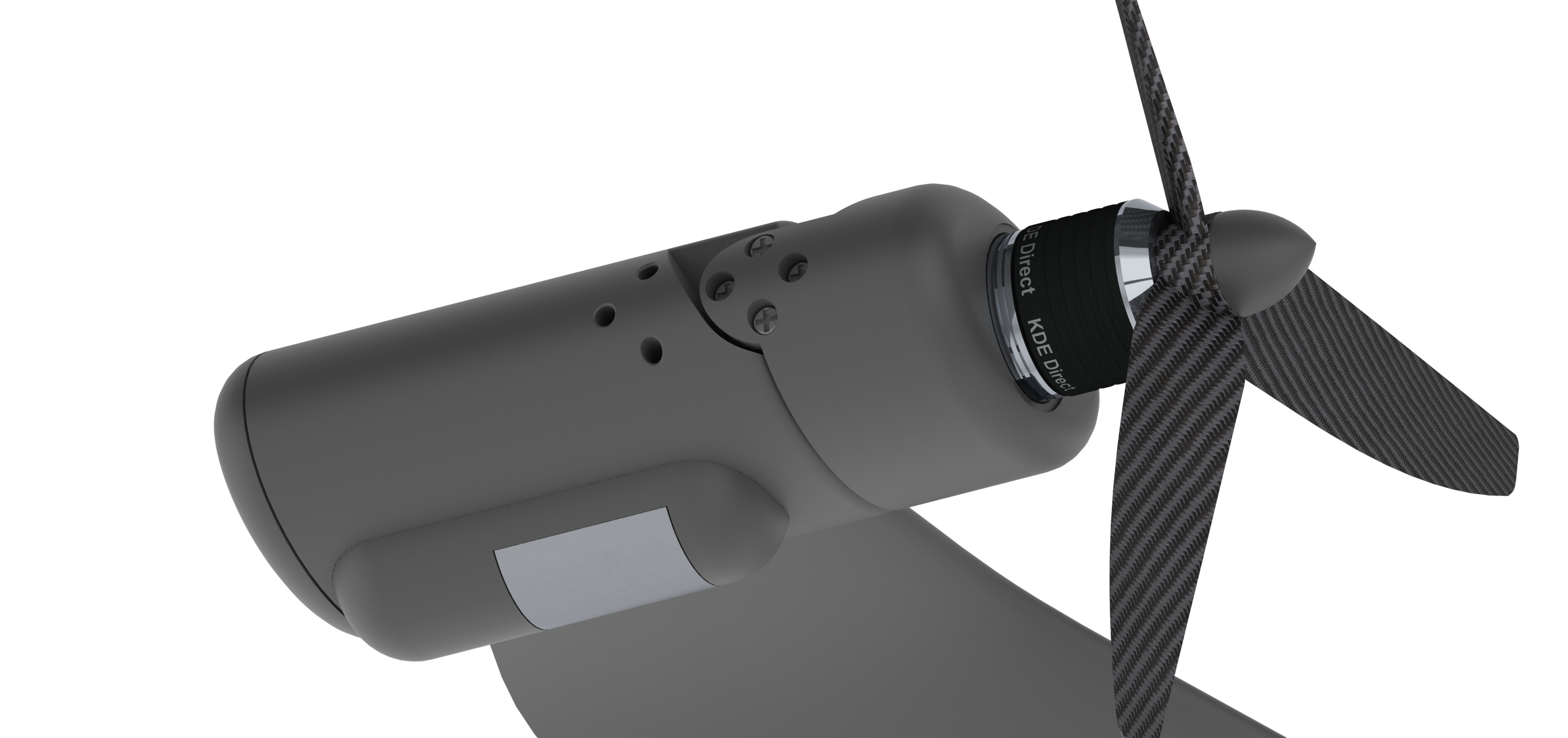
I have been a little quite lately because we hit a minor speed bump being that our front motor placement induced significant torsion stress on the inner wing structure. To overcome this we designed a totally new wing structure that pushed Solidworks to its limited and chewed up over 2000 hours of computational time. I am happy to say that the test section of the new core drastically surpassed our expectations not only in lightness but also in strength.
The good news is that we can potentially lighten the core even more than we first thought.
This is the core segment without its carbon skin.

2 Likes
Thanks for posting the pic. Was your section printed with PLA? What are the dimensions and weight of that section (hard to tell from the pic)? Why are you covering w carbon and not just 3mm packing tape? I assume you’ve seen this fabrication technique here https://www.3dprintedrcplanes.com/kodo/? He uses a cf spar.
The wing section was printed SLS using nylon 6 but the final wing will be printed SLS using Carbonmide. The full wing is 3.3m and the section above says we are on track for a weight of 2.9kg. The wing has to lift a 15kg UAV with a significant torsion force from the front rotors so the carbon skin was designed to add additional stiffness and structural integrity. What you can’t see in the picture is the capped sine-wave spar.
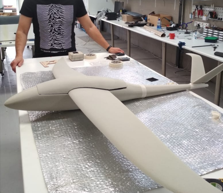
It’s been a while since the last updated but we are still moving forward. All of the CAD work and simulations are complete and we are a week away from the first flight trials of the halfscale airframe.
7 Likes
Hi, how much does the scale prototype weigh?
1.5kg with servos, receiver and batteries. It is pretty much a solid foam constriction
Is it a glass-reinforced foam construction?
Polyurethane with carbon wing spars and a carbon tail boom. The air-frame is then coated with epoxy resin and re-enforced with fiber tape where necessary.
1 Like
First flight test, a gliding test to check for anomalies and refine CG was today and was an incredible success. The UAV just seems to want to jump into the air and while we have work to do on the control surfaces it is an absolute pleasure to fly. The team is ecstatic with the result, even more so given that this went straight from computer to flight with no testing. All simulations were done in Solidworks CFD and they were pretty much spot on. Our Aerodynamicist Dr Becker van Niekerk got the wing design Spot on.
Video from the flight is here
https://www.dropbox.com/s/vna8b19aenx0xh2/Drone%20test%20flight.mp4?dl=0
3 Likes
Congratulations! I’m following this project with interest. Keep going!
Same here. Can’t wait to see how it performs in the field, I really hope it helps you guys.
Thanks, we are making good progress with the 60% scale and hope to have this deployed ASAP to start gathering data to assist with the build of the full scale version
Hey Robert, this looks very promising, and good weight. Did you go for the 3D-printed wing structure for this prototype? Did you use vacuum lamination technique or “just” hand-laminating and free-air curement?
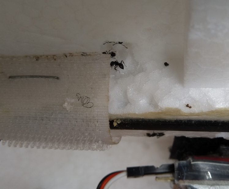
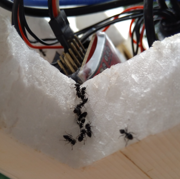
A warning if you’ll be flying this anti poaching drone in Africa: ants love to eat EPO foam as we experienced ourselves:
2 Likes
Thanks for the heads up, fortunately our latest airframe is fully MJF printed in PA12
In fact, that might be a good and valuable observation for future manufacturing procedures: as such, I am thinking about the potential to produce fully composite airframes out of laminated EPO cores, emptied by ants - just perfect 
1 Like
We opted for a higher tech approach (although if you could train the ants do do precision work its a cheap option  ). HP’s new MJF printer is a game changer although it still has two big limitations being build volume and material option. We have worked around both and the sample wing and fuselage sections are magnificent to say the least.
1 Like
So today marks the day where the air-frame design is locked down. No more changes for now, just some work on the control surfaces and servo bays and then off to MJF print the sections and assemble the first actual air-frame and begin powered flight testing.
3 Likes