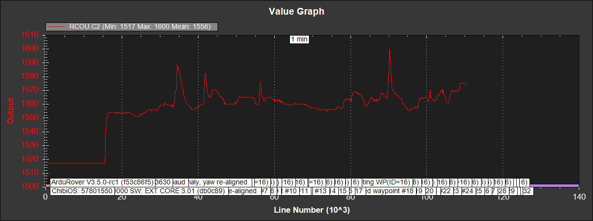
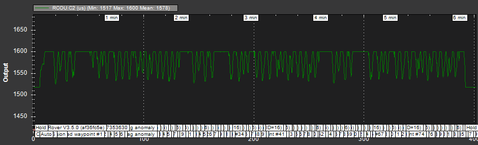
ArduRover on real competition R/C 1/10 car on real circuit: missions. FAR FROM WORKING

Indeed, testing in the big circuit, with CRUISE_SPEED up to 4.5 m/s RCOU.C2 reaches SERVO2_MAX=1600, so it is clipped. But speed regulation is not important now, and the results on the big circuit with RTK are reasonable, although just in one last test. The point now is to follow the desired trajectory reliably with RTK. The car hits the barriers constantly in these tests, so it is not convenient to reduce SERVO2_MAX.

So I started tests on the 2m wide circuit, and the results are not consistent. And because of the ChiBios problems with µSD cards I have not got yet long logs.

This is an example of RCOU.C2 on the 2m wide circuit. With CRUISE_SPEED 1.1 m/s it is rarely clipped, although the log is short:


RCOU.C2 has a minimum of 1517, which corresponds to SERVO2_TRIM. I have not tried yet to insert DO_CHANGE_SPEED waypoints, and have no idea if the car can brake. I haven’t tried either DO_SET_REVERSE waypoints, meant to drive in reverse. These type of competition cars don’t have reverse, so if this implies pulse under SERVO2_TRIM the car would brake.

Perhaps Randy can clarify braking.

I think that proves throttle clipping is not a problem. On a side note, the output seems to be demanding high acceleration and jerk in a few spots (around sample 90000 for example), which by itself is perhaps a symptom of the problem.

I still think reducing the waypoint radius would help behavior on the 1/18 track. The current diameter of each circle is the entire width of the track, allowing close approach to the barriers to be a valid solution. Some of the circles even overlap, which I think would validate vague paths.

I encourage reducing the waypoint radius to 0.2 m and trying again on the small track.

1 Like

Can you post your most recent log? I’m interested in helping.

Here is a long log of a 10x32 mission (10 laps) in the 2m wide circuit:
Rover_20181214_RTK_Asoger18_12.bin (100 MB)

There are two runs, whose videos are:


On the first video, initially the car had to be constantly put in place; this improved for whatever the reason, and recording was started, so not all waypoints appear. The second is moreless complete (the mobile phone used has a 10’ video limit, so recording has to be restarted, losing some seconds, and later joining videos.

The tlog’s are included in both videos.

The red flashing led on the GPS on top of the car indicates “rtk float” (steady on indicates “rtk fixed”).

As seen, the laps are irregular: bad laps, with car knocking the barriers and even being stopped, car completely out of trajectory, and good laps indicating that coordinates used are moreless correct (perhaps waypoints 8+32n can be shifted 1m south).

POS+waypoints:

On the average, perhaps the number of detected satellites increased from the first run to the second:

With respect to the irregular waypoints linkage, it can be related to this:

First, I think you should pay attention to the following thread: John Easton's battle with 'Wobbly Path' - [NOT SOLVED]

Second, I notice that you have some P-oscillations in steering. Decrease ATC_STR_RAT_P by 50%. Your actual steering rate is matching your desired turning rate, so that is good (FF-gain is set very close to correct).

Your TURN_MAX_G is set to 0.3, and I think this is far too low (causing your car to try to turn at all times rather than hit the navigation lines and stay on them). You need to get your car to hit its desired heading on the line VERY quickly so that you have precise control of the navigation. Then from there you can “soften” things up. Right now your navigation is “sloppy,” and I think in part it is due to TURN_MAX_G and maybe NAVL1_PERIOD. Your navigation is so “quick” that I think NAVL1_PERIOD may need to be <5.

Thanks a lot for the link and your comments about parameter adjustments, not only valuable for car behaviour improvements, but also for understanding their meaning towards a better knowledge of all this. I will test these changes shortly.

In fact, the steering oscillations are clearly seen on some instants on the videos, and I had occasionally seen them also in the big circuit.

However, I’d like to know how to make the car behave always the same, good or bad, but the same. There are good laps and bad laps, and the second run is better on the average. There are more satellites on the average on the second run, and the tlog part of the videos (starting on both at 20") clearly show the good and the bad laps.

The 2m wide R/C car circuit is on a corner, surrounded by tall trees.

HDop is on the average better on the second run:

Observe carefully instants following t=165 on the second run:

While in a good lap, the car suddenly loses trajectory and then recovers. Down and left in the video are shown HDop and Sats, which increase and decrease briefly respectively and then recover. This is a capture once recovered:


(Captured after recovery)

The car is using three compasses (the one on the RTK GPS is not connected):
-Two external at the front bumper, away from the motor.
-The Pixhawk internal one (perhaps should be disabled).

The GPS is above a copper plane, now floating. Perhaps it should be grounded, and the GPS ground connected directly to it.

Would it be convenient or possible to filter the GPS or compass data to avoid sudden trajectory changes?

BTW, this is the version used:
ArduRover V3.5.0-rc1 (f53c86f5)
PX4: bcbd027a NuttX: 1472b16c
PX4v2 00320046 35365118 37353630

With NuttX, no µSD card logging problems.

The key in my opinion is to make sure your steering tuning is spot-on sot that way you can clearly tune the navigation and GPS settings. Once you get rid of the oscillations, then we can move forward.

https://docs.emlid.com/reach/antenna-placement/ tells me that you might want a larger ground plane to receive better satellite data. My Here+ and Emlid Reach RTK GPS units on my plane have very low HDOP readings, but they have a very clear sky and multiple constellations enabled.

Here is yours:

Regarding GPS readings, you might want to try different values for GPS_NAVFILTER. Try 8 and see if that makes any difference.

You might also consider adding an elevation mask to the satellites you receive because satellites that are low in the sky may be giving you bad position data. (GPS_MIN_ELEV). Try 20 to start.

To extract more consistent data from your GPS, it might also require turning down the position rate: GPS_RATE_MS to 200 or 250.

This in combination with changing GPS_GNSS_MODE might help you get more satellites. With the Emlid Reach M+, I know that GPS, GLONASS, and QZSS satellites could be reliably logged at 5Hz (200ms). If you added more constellations, you might have to turn down the logging rate to 1Hz (1000ms) or it would skip GPS events.

https://docs.emlid.com/reachm-plus/common/reachview/rtk-settings/

1 Like

After three sessions more or less successful, it seems that the cause for the car going really bad is the RTK station mount point chosen: there are significant differences.

On the first session all went bad. Changing the ground plane, connecting it to electrical ground or not, disabling the internal compass and changing parameters didn’t make significant changes. As suggested, I finally left ATC_STR_RAT_P=0.3 (previously 0.5), which seemed to stop steering oscillations.

On the second session I got two good runs:

1.1m/s:

1.3m/s:

Including the hud undocked in these videos with the tlogs may give clues.

Rover_20181218_RTK_Asoger18_36.bin
Rover_20181218_RTK_Asoger18_37.bin

The third session was dedicated to the five possibilities for the RTK station mount point. They are described elsewere and are physically different, and one of them is virtual (which gave the worst results). It must be taken into account that they are meant for different needs and which can be very far away from the RTK physical station, but for these tests the distance is 14 Km.

This is the tlogs video with the hud at 1x speed:

These were the trajectories obtained with two of the mount points, which were unacceptable (the second one is virtual):

This other was a bit better:

This other was almost acceptable:

Finally, these were two runs with a mount point with good results:

So the conclusion is first of all if having several mount points, try all and choose the best one. I wonder if there is any parameter (as hdop and satellites for the GPS) to evaluate the quality of the mount point connected, since what appears in Mission Planner RTK screen showed good data for all above mount points.

1 Like

Wait, your the baseline to your base station is 14km?! That’s a fairly long ways for L1-only, and with a horizon surrounded by trees, I can guess that the GPS navigation would be a little less reliable. With a local base station <1km away, I would guess that you could actually get a GPS fix (instead of bouncing between 3D fix and float all of the time)

We can see GPS.Status in log 36 bouncing erratically between 4 and 5. I’m assuming 4 means DGPS and 5 means RTK.

Looking at GPS.Status from the quadcopter log in August Simultaneous_Copter_20180822_30.bin, we can see it is rock-solid at 4.

Is it possible to defeat the RTK to see how well that works? The quadcopter seemed to work fine without it. I think that would be a worthwhile experiment.

Alternatively, I would bring the car closer to an RTK station, say within 1 km, and attempt Auto driving some waypoints. I’m envisioning something simple in a parking lot near the station. First see if GPS.Status stays constant at 5. If so, then see how well the car stays on the waypoint path. If not, then pursue electromechanical fixes to get it steady at 5. If not steady at 5, then using RTK is maybe actually hindering progress.

4 is 3D Fix, 5 is RTK Float, and 6 is RTK fix. Roughly 2.5, 1, and 0.1 m accuracy respectivley. Bouncing between a RTK float and GPS is going to have a lot of movement because non-RTK position is uncorrected. It would actually be better to totally eliminate RTK because of the on-off nature of signals that are being received.

1 Like

1 Km?
Placing the base
Typically the distance between the reference station and local rover shouldn’t exceed 10-15 km…
The circuits are 14 Km away.

This is GPS Status with the same GPS installed on a drone moreless 15 Km away from the RTK station with a clear sky:

This is GPS Status with the same GPS on the car on the big circuit on the succesful mission above:

That is the RTK station I have. The circuits cannot be moved and the trees cannot be cut. With the RTK GPS the targets are:
-On the big circuit add DO_CHANGE_SPEED waypoints and improve lap time. How can I brake the car?
-On the small circuit try a Balance Bot:
GSoC 2018: Balance Bot with Arduino
if knowing how to make it work with stepper motors (not DC motors).

Now with the best mount point I get acceptable results on both circuits, and even I could drive an 1/8 R/C bike against the car doing this mission:


Clearly the 1/8 R/C bike wins.

On four of the five mount points available Mission Planner shows the RTK station coordinates with many decimal points (same as the coordinates published by them). On the virtual one MP reports a virtual station 4 Km away from the circuits; however the results are the worst. I’ll consult the RTK station people about this.

I suggested that as an experiment only. Information gathering. Data collection. A quick way to figure out whether RTK lock is the only problem with the car or not.

Imagine if you ran my proposed experiment, RTK proved solid at status 6, yet the car still occasionally wandered. You would say, “Aha! I just wasted several months fixing something that was not the root cause.”

Imagine if you ran my experiment, and RTK was still jumping around from 4 to 5. You would say, “Aha! The problem is not distance from the station or trees, but maybe an intermittent electrical connection.”

Maybe the experiment would show solid 6, and the car is cured. You would say, “Well, there is the problem but until Ardurover developers can fix the guidance algorithm to stop being so sensitive to change in GPS status, I need to give up on RTK altogether and rely on DGPS only.” After all, the quadcopter worked fine without RTK, right?

No matter what, in one test session you would get a wealth of information. In my opinion it would help identify a solution quicker than the approach you have been taking.

I hope this helps. I want to see your car running lap after lap at 20 m/s held to the path like a slot car!

New experimental experiments:
-Two RTK GPS’s on car.
-Tests on RTK station.
-Swarming.


Two RTK GPS’s on car.

Having got another XL RTK GPS for mounting an offroad rover, I first tested it as a second GPS on actual car. At the same time, reference station was improved (Glonass added on a mount point, and perhaps something else).

Recall that on post 37 july 2 above I had problems with a single GPS (conventional), with no clear reason.

These are the results with two mount points (good and almost equal) on the 2m wide circuit at 1.3m/s:

With these good results I tried at 1.6m/s:

It is clear that speed was too big. The car had to be repositioned many times.


Tests on RTK station.

Better than trying on a place closer to the RTK station, I tried on the RTK station helped by two people working there, who were very kind and showed great interest on these experimental experiments, with both RTK GPS’s on the car.

The reference point appearing on Mission Planner is at the white dome on the center of the photo. I tested the car on a rooftop moreless 40m from it.

Results were not so good, but this was a first contact:
-RTK fixed (status 6) was difficult to get.
-Fewer satellites than at the circuit.
-The new RTK GPS was on RTK fixed more often than the old one, and with its logs more stable.
-The expensive GPS instruments they had were affected by the 433MHz 3DR antennas. A final test was done without these antennas, with the Pixhawk connected to the laptop with an USB cable, and the car quiet.

Later I saw that from a previous test I had GPS_MIN_ELEV = -60, so for a next test I will leave the default value. This next test will be a mission at moreless 1m/s, since, although there was not too much space, I could drive the car:

This is the tlog video:


Swarming.

I have added to simultaneous copter rover mission video (post 57 august 22) above the tlog videos:


Unfortunately:
-the copter lost waypoints (irregular waypoints joining);
-the antennas on car and drone were horizontal (this will be changed), and communication was lost at times.

Instead of having a common mission on drone and car, and start each one independently (first car, next drone) I plan to try swarming with car being the leader and drone the follower. I don’t know if this can be done, and if the drone will follow the car being it at 0m height (perhaps offset when “Update Pos” button is pressed, with drone above car, would be maintained).

So I asked this on:
Swarming with Mission Planner

Response: the Empty Set ø.
Empty Set ø (Wikipedia)

1 Like

Rover-Copter swarming: seems to work. This is an initial test:


The car was not armed (moved by hand).

On all tests above from day one the 433 MHz antena was horizontal, since it was mainly used for programming the Rover, and was easier to place. GPS’s on roof were separated from electronics, but not too much, since their compasses were not used.

But these 3DR 433 MHz antenna seem to affect GPS RTK lock. With CellSensor:

Posts: 100 mm. Small 433 MHz antenna in vertical position for a better overall data transmission. GPS Status was continuously 5 (RTK float) during this test, being acquired fast.

Above:
“…The new RTK GPS was on RTK fixed more often than the old one, and with its logs more stable…”
What probably happened is that the old RTK GPS was closer to the 433 MHz antenna than the new one.

1 Like

Here is another video (4K) with the two RTK GPS’s on the big circuit, with the two 3DR antennas vertical (no data loss as can be seen on the tlog interval), and with both GPS’s raised and with beter shielding:

Log:
20190211_RTK2_Asoger_92.bin

Speed was increased to 4.7 m/s, which resulted critical:


Speed changes are clear in above video.

Although both GPS’s status was 4 or 5 during the mission, it was seen as 6 (RTK fixed) occasionally during the rest of the session:


That happened roughly during 15s, with the car stopped.

The mission starts beside the drivers rostrum, so the car passes three times beside it on the three laps mission, and an aditional one till reaching the final waypoint. GPS shadowing is clear there:

At 4.7 m/s desired cruise speed it is hitting your throttle servo limit often.

This results in the actual speed to never reach the desired speed. I would think this is imposing a lot of error on the control loop.

I recommend relaxing SERVO2_MAX limit so 4.7 m/s is more easily within the capability of the car. I think that would result in tighter control and more stability.

I noticed something in your logs. Accelerations measured by IMU1 seem nice and quiet but IMU2 is quite noisy. Look at this period when the vehicle is at rest. IMU2 has X-acceleration noise exceeding ±0.05 m/s² while IMU1 noise is around ±0.01 m/s².

Same thing for Y-acceleration. IMU1 is nice and quiet while IMU 2 has 8 to 10 times the noise.

What is your hardware setup with regard to accelerometers and connected wires? Do you indeed have two sets? Is one of them subject to more electromagnetic interference than the other?

I think that reducing noise on IMU2 or disabling it would do two things. First, it would clean up the calculated position estimate, and second, it would enable reducing parameter EK2_ACC_P_NSE, which would make the Kalman Filter trust the IMU more and the GPS less.

Same thing with your gyros. Look how much noisier IMU2 gyro is, again when the vehicle is not moving.

Limitation:
SERVO2_MAX=1600
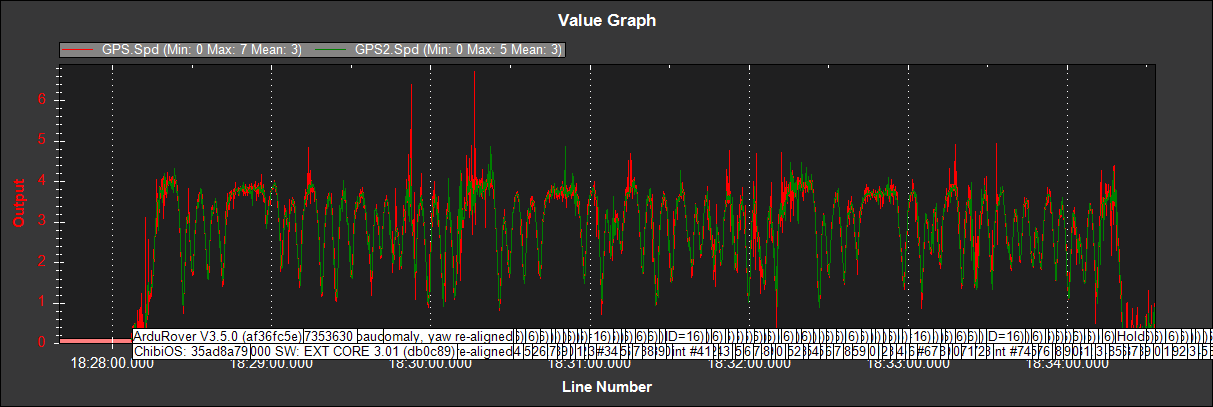
which is reached frequently as seen on RCOU.C2.

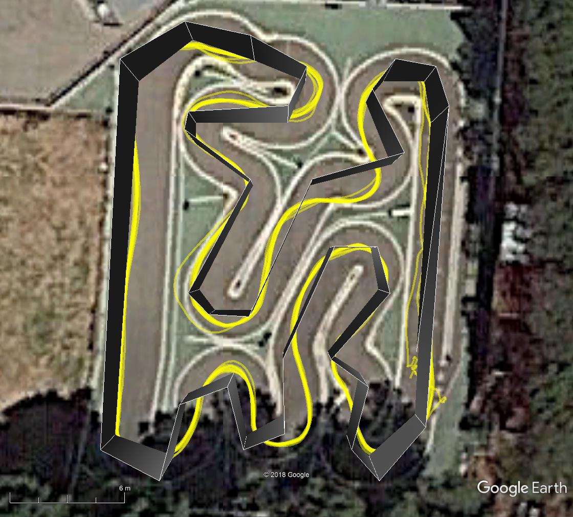
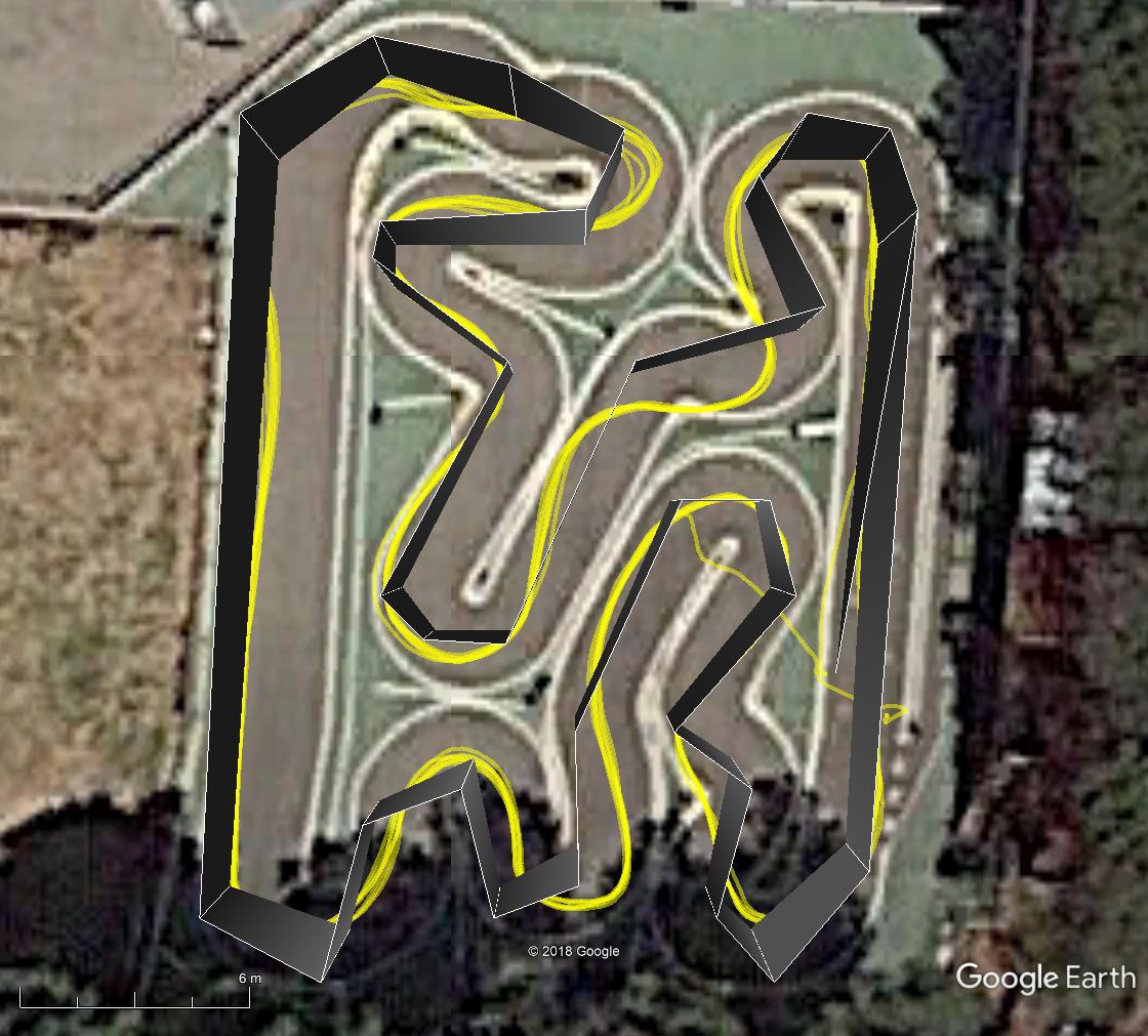
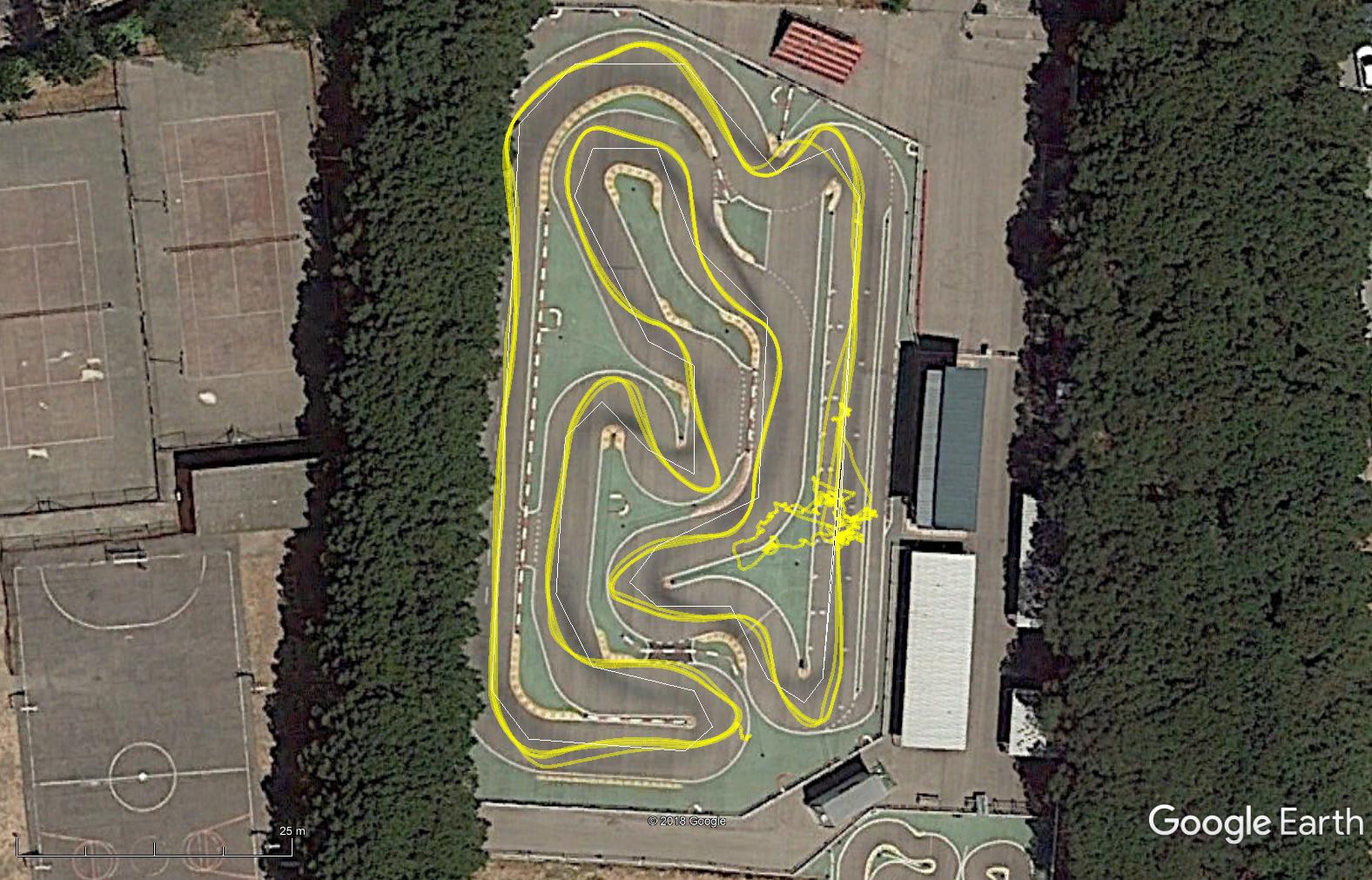
I’ll increase this. However, with CRUISE_SPEED=4.7 and not having inserted DO_CHANGE_SPEED waypoints, the car simply goes too fast (in another test, also at 4.7m/s, the car was stopped at a barrier), as well as at 1.6m/s the car went too fast at the small circuit.

Also:
SERVO2_MIN=1000
SERVO2_TRIM=1517

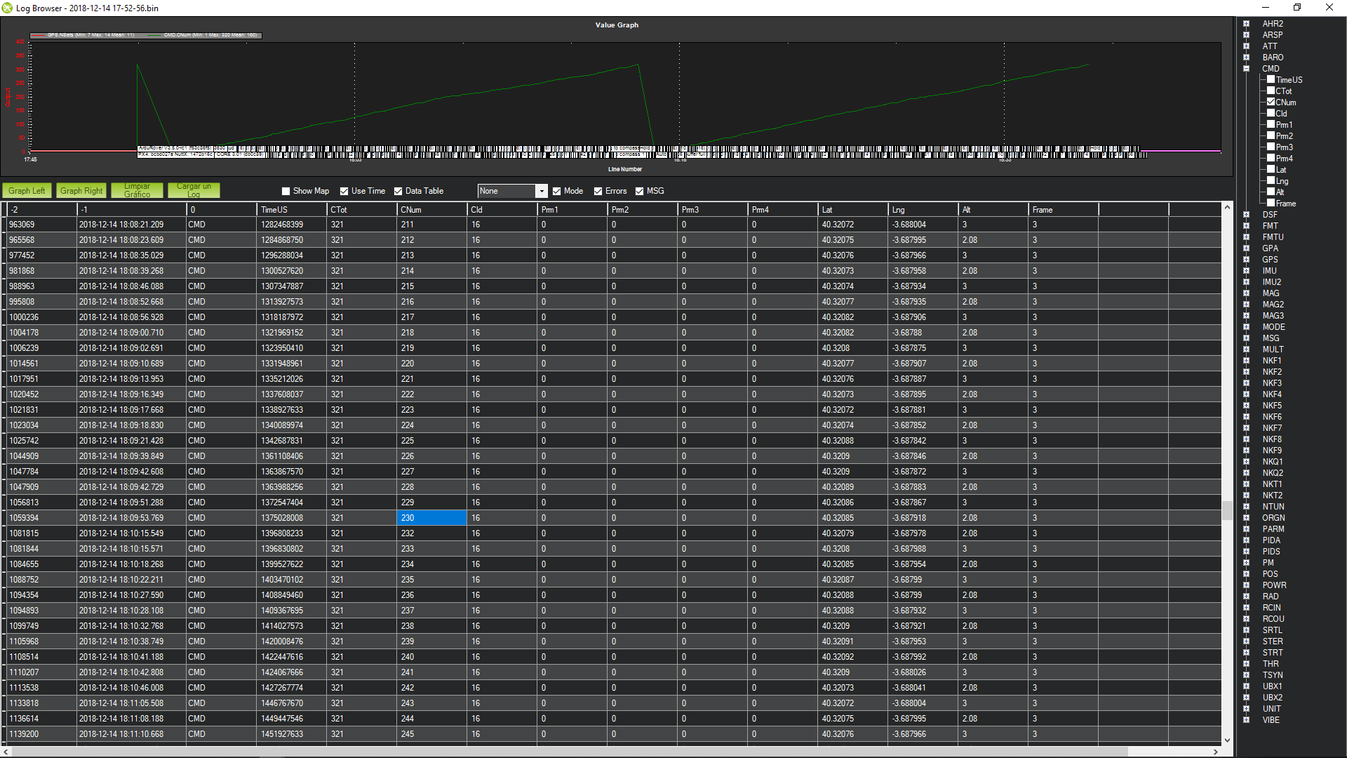
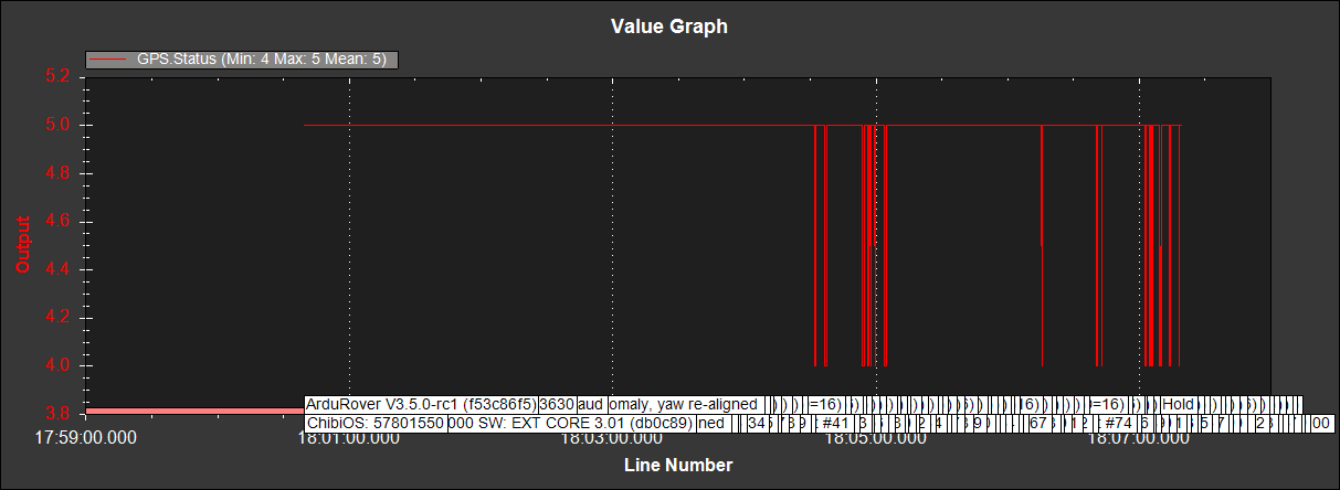
Minimum RCOU.C2 is seen as SERVO2_TRIM: the car does not brake. Above (december 18):
“… On the big circuit add DO_CHANGE_SPEED waypoints and improve lap time. How can I brake the car?…”
No answer.

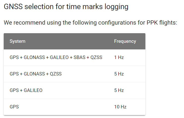
These are the waypoints types:
waypoints_types
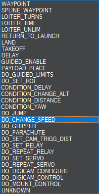
I wonder if a DO_CHANGE_SPEED with a negative speed would make the car brake, making R2.COU go under SERVO2_TRIM=1517.
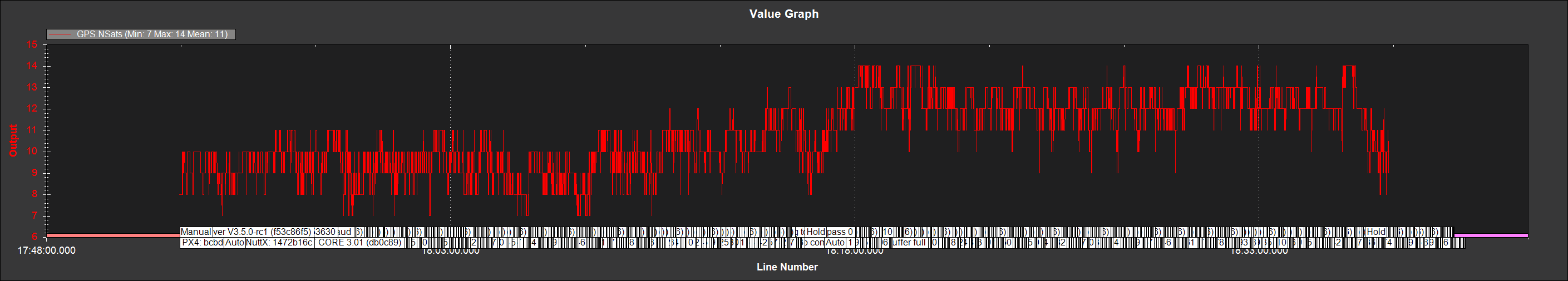
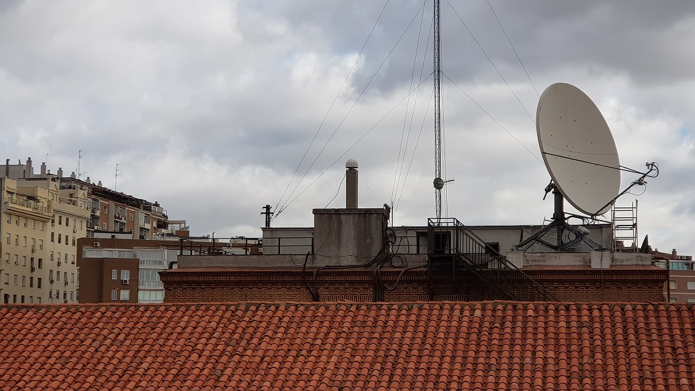
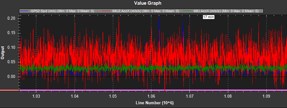
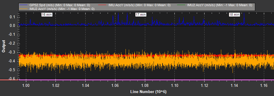

…What is your hardware setup with regard to accelerometers and connected wires? Do you indeed have two sets? Is one of them subject to more electromagnetic interference than the other?..

The controller is a Pixhawk, with the adition of two external compasses. The probable sensors are as follows:

From the Pixhawk documentation:
Sensors:
-MPU6000 as main accel and gyro
-ST Micro 16-bit gyroscope
-ST Micro 14-bit accelerometer/compass (magnetometer)
-MEAS barometer

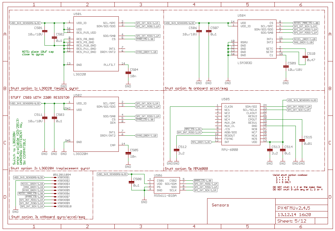
The MPU6000 and the MEAS barometer are clear in the schematic above (MPU-6000 (from Invensense) and MS5611 (from TE)), but not so much the ST components.

From ST documentation:
L3GD20H: 3-axis gyroscope, I2C/SPI digital output, low-power 3-axis angular rate sensor, 16 bit rate value data output, I2C/SPI digital output interface.
LSM303D: 3D accelerometer and 3D magnetometer, 16-bit data output, I2C serial interface

So the ST Micro 16-bit gyroscope in the Pixhawk documentation should be the L3GD20H in the schematic, and the ST Micro 14-bit accelerometer/compass (magnetometer) could be the LSM303D in the schematic, being “14.bit” an error.

What is labelled X503 (offboard gyro/accel/mag), being others labelled Uxxx, should be an SPI gyro/accel/mag (I don’t know which), but I have not added anything like this.

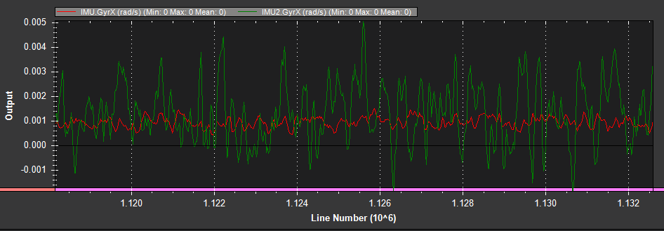
So IMU1 and IMU2 are those inside the Pixhawk, moreless in the same conditions (at different distances from the 3DR antenna or the motor). Being from different manufacturers (Invensense and TE) they may behave differently.