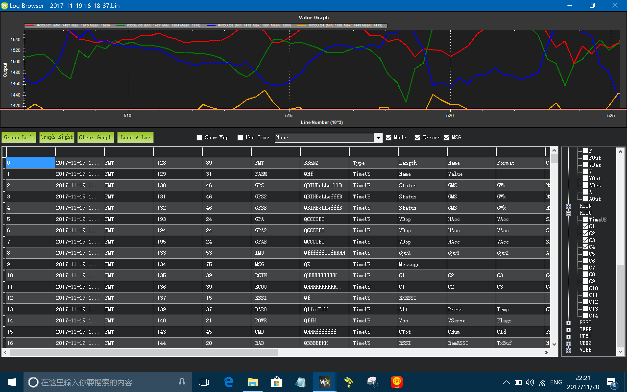
It is pretty clear that the RCOUT curves don’t have the same oscillation issue, so logically it has been nailed that it should be a mechanical problem, right?
I will replace some of the key mechanical parts like the rotor head and blades to see if the vibe can be eliminated. Thank you again!
I don’t know that you have to replace anything. Tuning dynamic “wobble” out of a helicopter main rotor is somewhat of an art, not a science. Most times it’s “good enough” to not cause an issue. But it can be caused by anything from a slightly bent mainshaft, to worn head dampers. What I like to do is put different color tape on the leading edge of the blades - maybe red on one and green or silver on the other. Hover the heli and observe the rotor disc edge-on. If the green blade appears to want to track above the red one, for instance, reduce the pitch on the green blade with the pitch link.
You can set the pitch on the bench with a digital pitch gauge and most times it’s close enough. But for a really smooth running heli dynamic tuning of the pitch/blade tracking is almost always required.
At the RC club, tuning turbine scale models with 4 or 6 blade rotors that are 2-3 m diameter, we have even used a GoPro at high frame rate and spent a whole afternoon tracking a 4 or 6 blade rotor to get it scale smooth.
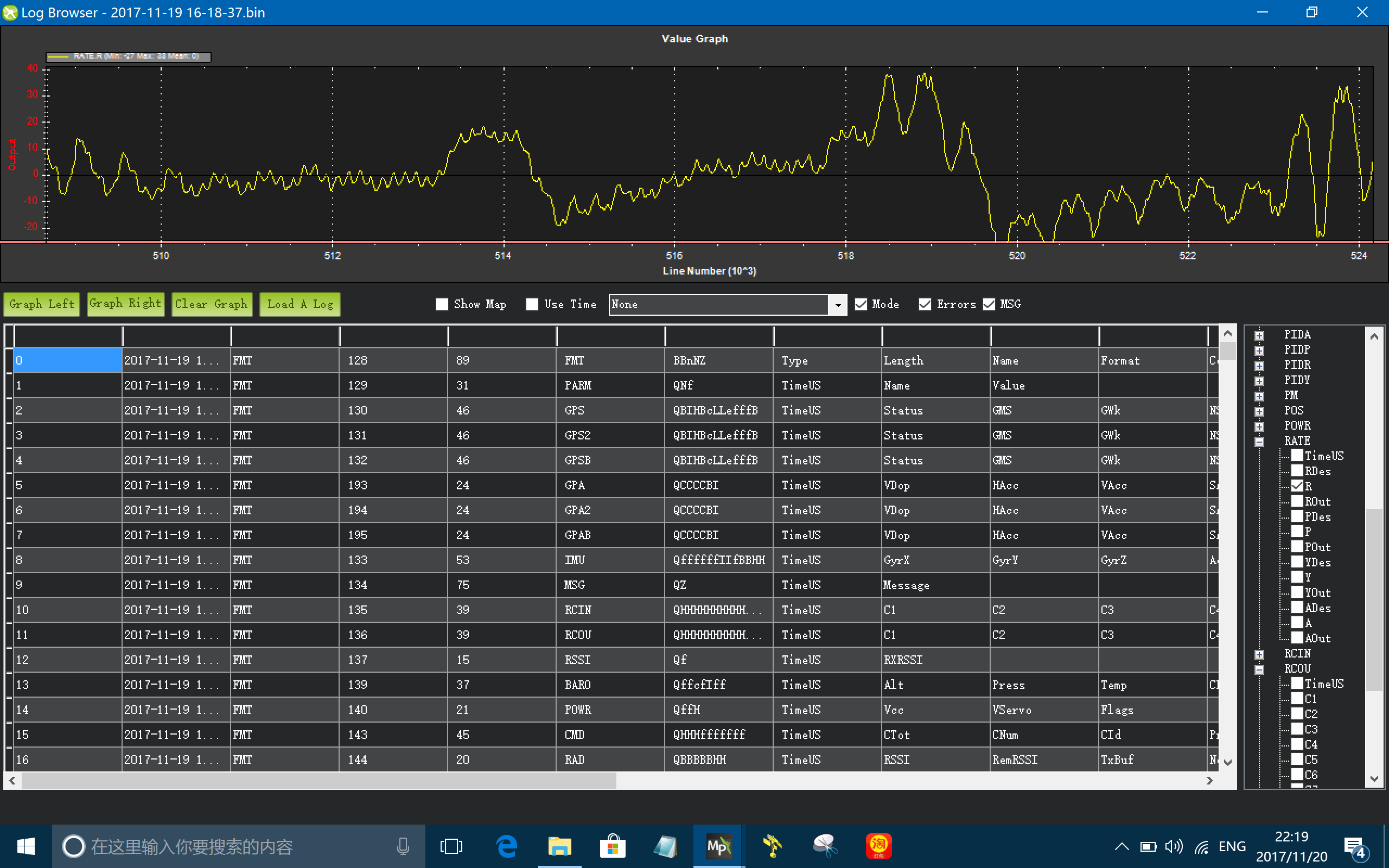
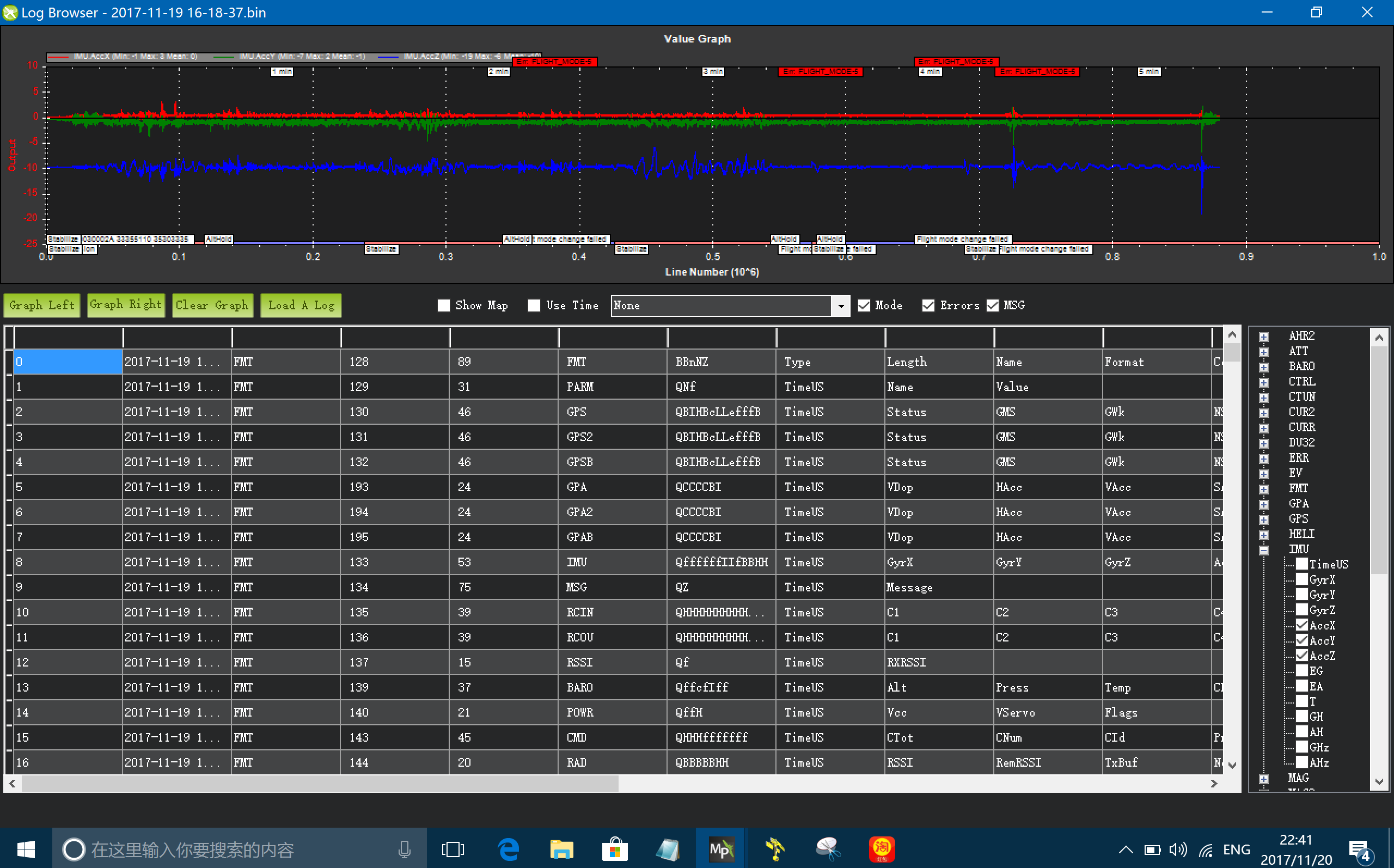
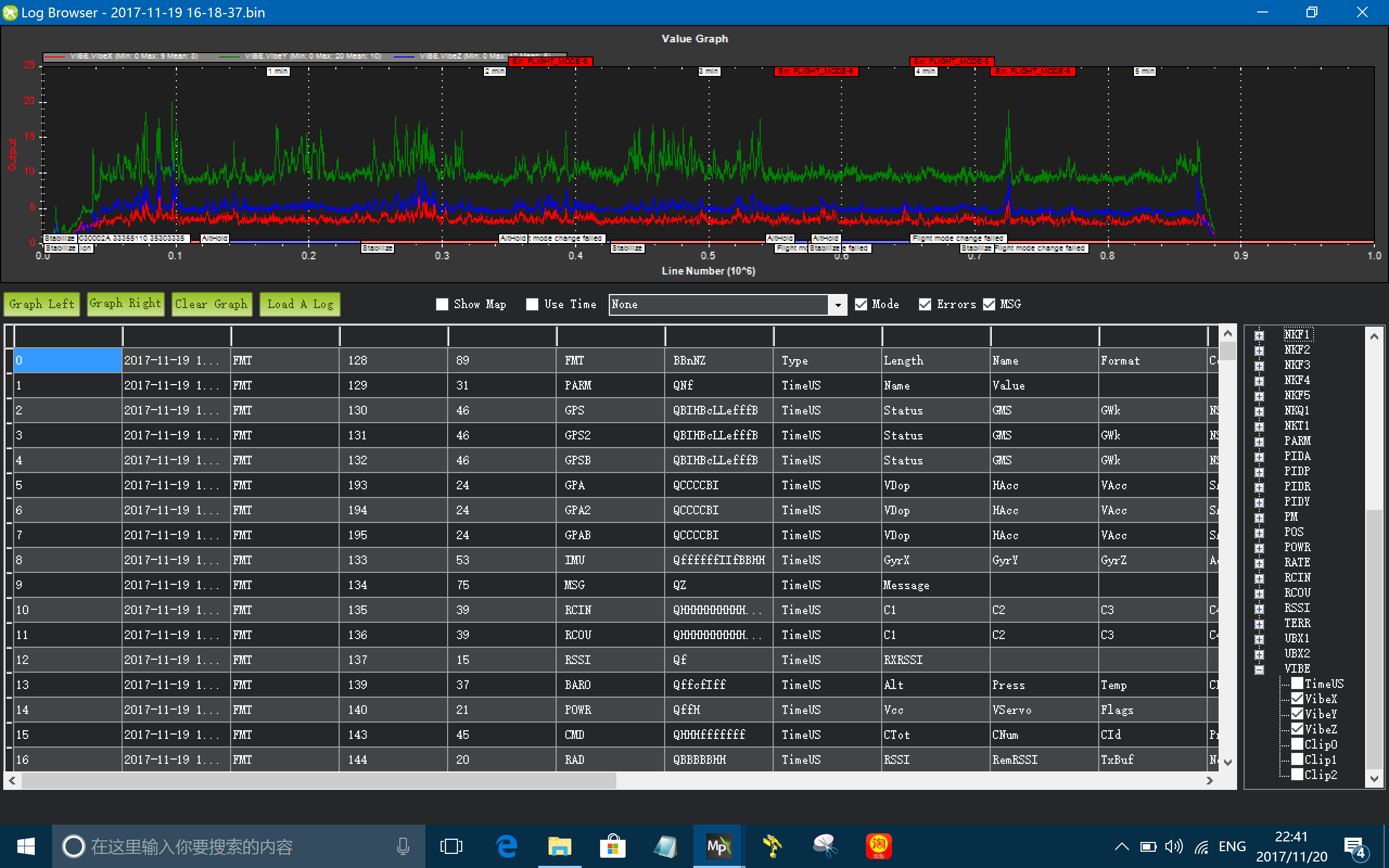
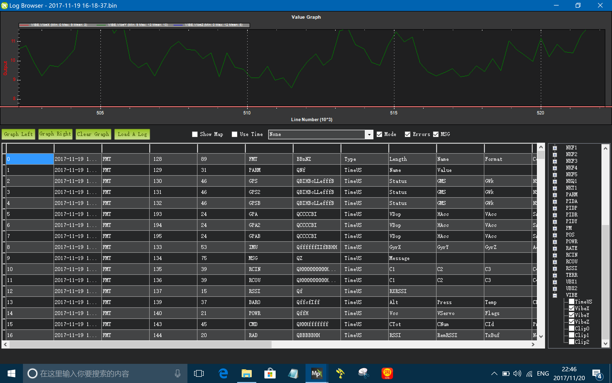
Thank you for your suggestions! Yes, I don’t see the oscillations in the actual flights. I did what Chris suggested to compare the RCOUT curves in the log to the RATE R curve, and it is very clear that the RCOUT curves don’t have oscillations similar to the RATE R. And the VIBE levels in my log is like this:
Something else weird that I just discovered: if I set the RATE R and VIBE Y curves to the same temporal scale, I don’t see the same oscillation on the VIBE curve as well…
Yes, I know this method of using colored tapes to tune the blades, I will definitely give it a try. Since the kit is brand new out of the box, I believe the shafts are not likely to be bended though.
I doubt that for a SAB Heli Division machine. Those are usually pretty high quality kits. Unfortunately, though, I have seen a couple of the lower quality kits come with a pre-bent mainshaft
That is just indicative of noise or different frequency vibration causing interference to the gyro output to the rate controller that’s not being logged. I have had at least one helicopter that I remember that had very good looking vibes in the vibe logging. But it would blow the EKF due to IMU aliasing and the rate curve looked way worse than yours. Changing the mount on the FC and isolating vibration being introduced by the GPS/compass cable fixed that one.
Yi,
Be careful in comparing these signals. The Vibe.y is a standard deviation of the y acceleration signal. The Rate.R is a gyro or angular rate signal. So not only are they are measuring two different things (linear acceleration vs angular rate) but the Vibe signal is a statistic where the rate.R signal is the measured value. Now that being said if your sensor is not at the center of gravity of the vehicle then angular accelerations can be seen as linear accelerations. But I still go back to the fact that the VIBE and Rate signals are inherently different.
Checked the main shaft and I believe it is alright. Started some more fine tunings of the tracking issue by using the colored tape method and will test fly once the rain outside stops, will try to provide a LOG file in couple of days. Thank you for your long time support!
BTW, I disassemble the rotor head today and found the thrust bearings on the spindle became sluggish. I replaced them with new parts. Don’t know if this can be the cause of the oscillation.
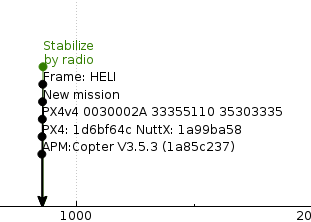
I uploaded the LOG of todays’s test flight to google, please have a look of it when convenient. I took off then did some hovering and gentle pitch & roll maneuvers. From 110 seconds I turned up the rotor head speed a little. Hovering collective pitch dropped from 9 degrees to about 8 degrees by this RPM speed up. https://drive.google.com/file/d/1KftAYgiQUPCCi6SACY7PlHtK081GWnxx/view?usp=sharing
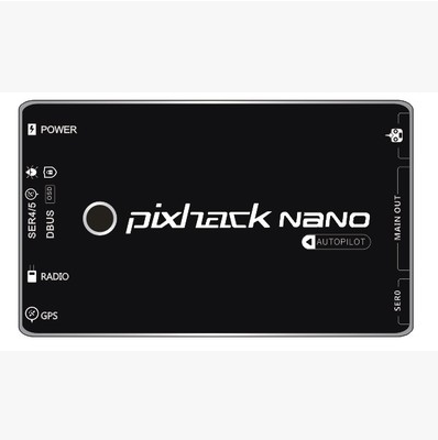
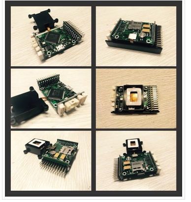
It’s a clone unit called Pixhack Nano. It’s the a single IMU controller with only 6 PWM outputs, but it has a built-in damping structure and it’s compact in size.
Yi
Other than being surprised it’s a -v4 flight controller, I didn’t see anything glaring in the logs. Obviously, since there’s only one IMU there’s not going to be any disagreement between IMU’s. If it seems to fly ok, the oscillation in the rate graph is probably not a big deal.
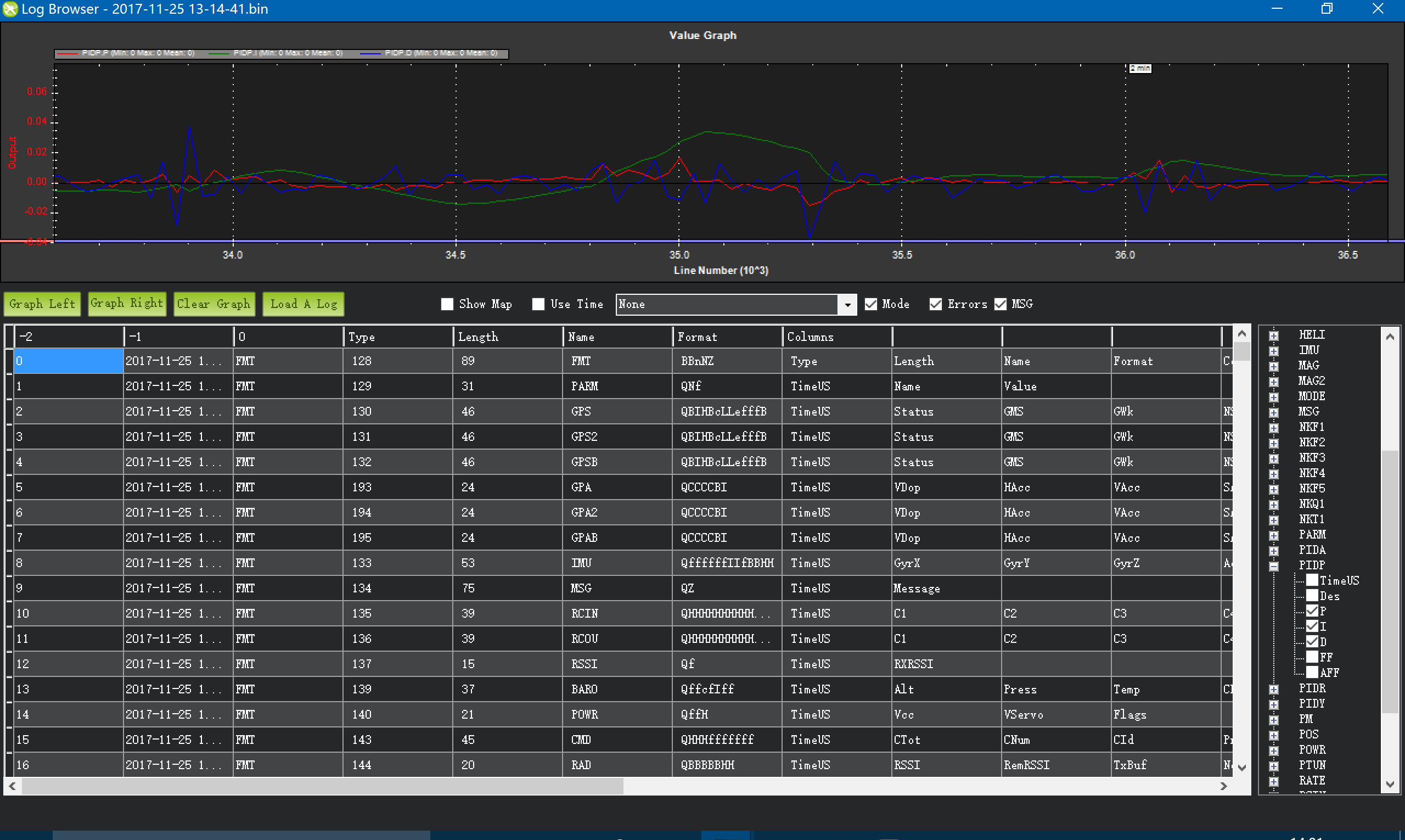
I was using CH6 to tune the kP of RLL and PIT but in the log, it seems the I and D gains are also experiencing dramatic changes. Is it normal? Once the I and D gains are set in the parameters, shouldn’t they just keep themselves as a strait lines in the LOG or a stable wave curve within the range of the parameters’ inputs (What I set was I gain @0.18 and D gain at 0.002).