Hey all.
I’m new to using the APM for anything having come from Quadcopters and the use of the KK and Multiwii.
I’m going to be using the APM for a rover project and wanted to know how to wire up the HC-SR04 module or should I shelve it and invest in another module?
Can I use more than one or will it not be of benefit?
Chassis is the SCT 1/10th brushless from HK so it has a nice big bumper for mounting the sensors.
Any additional info for a noob will be welcomed.
@rokit5,
Presently the ArduRover2 code is designed for sonar sensors that output a voltage that is proportional (or otherwise) to the distance to the detected object. I am presently using two Maxbotix MB1240s in the sequential triggered mode on my rover.
Regards,
TCIII ArduRover2 Developer
Here is an interesting IC, D/A converter IC 12 Bit SOT-23-6, MCP4725A0T-E/CH. Low cost ~0,85 €
Datasheet:
www1.elfa.se/data1/wwwroot/asse … ng_tds.pdf
@Riff_
In the world of rovers I have found that adding more complexity can be a detriment to reliability.
The Sparkfun 2012 AVC winning rover did not compete in the 2013 AVC because the ramp jump damaged his navigation hardware. I won the AVC Peloton Class with my Slash rover because I adhere to the KISS philosophy: Keep It Simple Stupid.
That being said, I would suggest that you might be better off finding distances sensors that provide a voltage output corresponding to the detected distance and let the APM do the work instead of adding additional hardware.
Regards,
TCIII Developer
Keeping it simple is always a good plan, I agree. But if you still need to use cheaper sensors You will need to add second controller board like Nano or similar that has PWM output.
I was little bit busy, learning to write c for Arduino, have not done that before. This is my first code.
Here is what I’m going to do:
[code]/*NewPing Created by:
Tim Eckel
NewPing original code
http://code.google.com/p/arduino-new-ping/wiki/15_Sensors_Example
Code modified for analog output by:
Raimo Noormaa aka Riff from EST
mcmatrix from EST
Code output is analog signal 0-5V. There can be multiple sensors, max number untested.
Arduino Nano Layout:
http://www.pighixxx.com/pgdev/Temp/nano.pdf
Available PWM pin : 3, 5, 6, 9, 10, 11
Available Digital I/O pin : 2 to 13
*/
#include <NewPing.h>
#define SONAR_NUM 2 // Number or sensors.
#define MAX_DISTANCE 400 // Maximum distance (in cm) to ping.
#define PING_INTERVAL 30 // Milliseconds between sensor pings (29ms is about the min to avoid cross-sensor echo).
unsigned long pingTimer[SONAR_NUM]; // Holds the times when the next ping should happen for each sensor.
unsigned int cm[SONAR_NUM]; // Where the ping distances are stored.
uint8_t currentSensor = 0; // Keeps track of which sensor is active.
NewPing sonar[SONAR_NUM] = { // Sensor object array.
NewPing(2, 3, MAX_DISTANCE), // Each sensor’s trigger pin, echo pin, and max distance to ping.
NewPing(7, 8, MAX_DISTANCE),
};
int pwmPins[SONAR_NUM] = {
9, 10 }; // an array of pin numbers to which pwm output is written
int led = 13;
void setup()
{
Serial.begin(115200);
pingTimer[0] = millis() + 75; // First ping starts at 75ms, gives time for the Arduino to chill before starting.
for (uint8_t i = 1; i < SONAR_NUM; i++) {// Set the starting time for each sensor.
pingTimer[i] = pingTimer[i - 1] + PING_INTERVAL;
}
for (uint8_t i = 0; i < SONAR_NUM; i++) { // pwm output pin counter
pinMode(pwmPins[i], OUTPUT);
}
{
// initialize the digital pin as an output.
pinMode(led, OUTPUT);
}
Serial.println();
}
void loop()
{
for (uint8_t i = 0; i < SONAR_NUM; i++) { // Loop through all the sensors.
if (millis() >= pingTimer[i]) { // Is it this sensor’s time to ping?
pingTimer[i] += PING_INTERVAL * SONAR_NUM; // Set next time this sensor will be pinged.
if (i == 0 && currentSensor == SONAR_NUM - 1) oneSensorCycle(); // Sensor ping cycle complete, do something with the results.
sonar[currentSensor].timer_stop(); // Make sure previous timer is canceled before starting a new ping (insurance).
currentSensor = i; // Sensor being accessed.
cm[currentSensor] = 0; // Make distance zero in case there’s no ping echo for this sensor.
sonar[currentSensor].ping_timer(echoCheck); // Do the ping (processing continues, interrupt will call echoCheck to look for echo).
}
}
{
digitalWrite(led, HIGH); // turn the LED on (HIGH is the voltage level)
delay(1000); // wait for a second
digitalWrite(led, LOW); // turn the LED off by making the voltage LOW
delay(2000); // wait for a second
}
// Other code that DOESN’T analyze ping results can go here.
}
// If ping received, set the sensor distance to array.
void echoCheck()
{
if (sonar[currentSensor].check_timer())
cm[currentSensor] = sonar[currentSensor].ping_result / US_ROUNDTRIP_CM;
}
// Sensor ping cycle complete, do something with the results. Location option 1 for code processing
void oneSensorCycle()
{
for (uint8_t i = 0; i < SONAR_NUM; i++) {
// turn the pin on:
// http://arduino.cc/en/Reference/analogWrite
analogWrite(pwmPins[i], cm[i]);
//        Serial.print(i); // print sensor number accessed
//        Serial.print("="); // = märk
//        Serial.print(cm[i]); // sensor distance value
//        see prindib reavahetuse ka lõppu, väljund hüppab järgmisele reale
//        Serial.println("cm "); // cm
//        Print format i = xxx cm
}
} [/code]
The code that I uploaded is a rough solution. Output is not very nice. So I made several modifications to software and hardware and I think I’m really close to a almost perfect solution. My code version is 2.3 
I simplified the code to remove any unnecessary lags, added mapping, added some filters. I have reached stable signal with an accuracy of ~ ± 0,5cm @ 30ms with two sensors. Things that probably need some attention is that result is not linear from 0 to 4 meters. So I had to find a compromise solution, I calibrated the sensors to work at the distance that I need to know accurately.
What I would have to say is that If I would have started with 39 USD sensors I would have reached one part of the goal much earlier but doing so I would have NOT learned how to program Arduino, build and use filters, assemble and design electronics etc.
Hey Riff_
any update about your reserach?
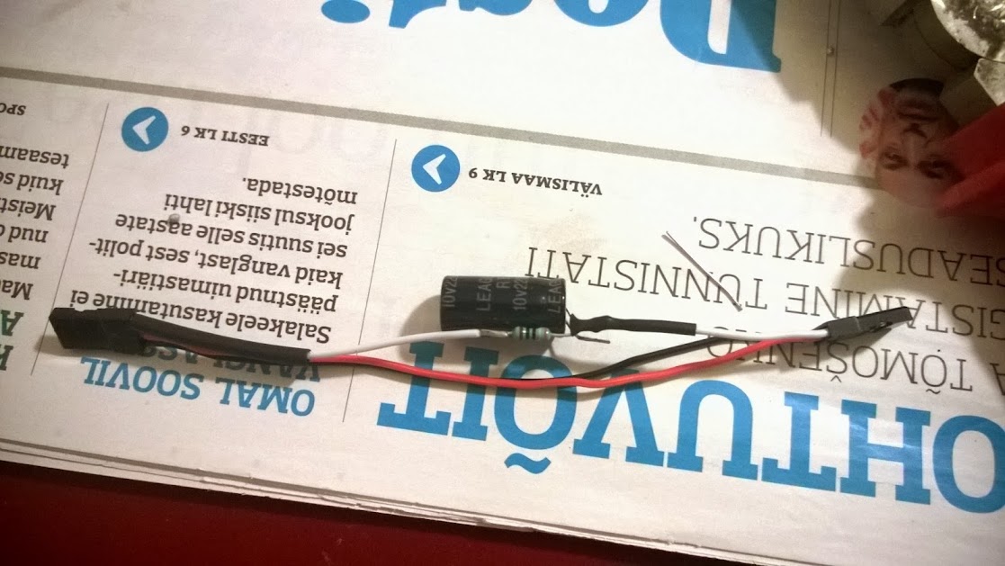
For me it works. I added mapping to the signal and a filter. Signal is smooth but filter needs some additional tweaking if fast signal is required. I have no need for a fast signal yet. I can get better reaction time if I play around with filter resistance and capacity, wrong resistance makes signal slow, does not allow capacitor to charge/discharge as fast as signal is generated. This is a small modifications just need to replace the Arduino -> APM/Pixhawk cable where I have integrated the filter.
Currently I’m using
390 oom
2200uF 10v
lh4.googleusercontent.com/-sG29 … 30_004.jpg
arduino-info.wikispaces.com/Analog-Output
I’m using Arduino Micro now.
[code]#include <NewPing.h>
#define SONAR_NUM 2
#define MAX_DISTANCE 400
#define PING_INTERVAL 30
unsigned long pingTimer[SONAR_NUM];
uint8_t currentSensor = 0;
NewPing sonar[SONAR_NUM] = { // trigger pin, echo pin, max distance
NewPing(5, 6, MAX_DISTANCE),
NewPing(7, 8, MAX_DISTANCE)
};
int pwmPins[SONAR_NUM] = {
10, 11 };
void setup()
{
Serial.begin(115200);
pingTimer[0] = millis() + 75;
for (uint8_t i = 1; i < SONAR_NUM; i++)
pingTimer[i] = pingTimer[i - 1] + PING_INTERVAL;
}
void loop()
{
for (uint8_t i = 0; i < SONAR_NUM; i++) {
if (millis() >= pingTimer[i]) {
pingTimer[i] += PING_INTERVAL * SONAR_NUM;
sonar[currentSensor].timer_stop();
currentSensor = i;
sonar[currentSensor].ping_timer(echoCheck);
}
}
// Other code that DOESN’T analyze ping results can go here.
}
void echoCheck()
{
if (sonar[currentSensor].check_timer())
pingResult(currentSensor, sonar[currentSensor].ping_result / US_ROUNDTRIP_CM);
}
void pingResult(uint8_t sensor, int cm)
{
analogWrite(pwmPins[sensor], map(cm, 0, MAX_DISTANCE, 0, 255) );
Serial.print("Andur ");
Serial.print(sensor); // print sensor number accessed
Serial.print(" = "); // = märk
 //        see prindib reavahetuse ka lõppu, väljund hüppab järgmisele reale
Serial.print(map(cm, 0, MAX_DISTANCE, 0, 255)); // sensor distance value
//        see prindib reavahetuse ka lõppu, väljund hüppab järgmisele reale
Serial.println(" cm "); // cm
}
[/code]
1 Like
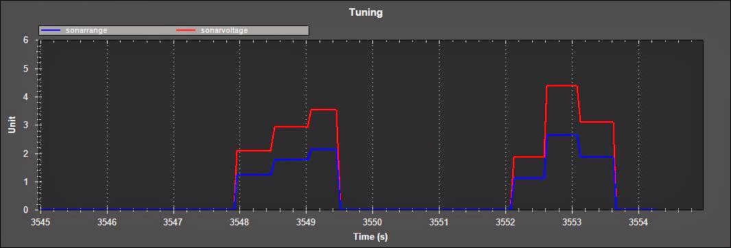
Text is in Estonian language but you will understand the units and values.
[quote=“Riff”]Koodi ei ole muutnud, kuid katsetasin veel erinevate kondensaatoritega. Sai proovitud 22uF, 330uF, 680uF ning 1500uF kondensaatoreid. Kauguse graafik stabiliseerus alles 1500uF juures.
ms - iga mõõtmise vaheline aeg
15ms 22uF
lh6.googleusercontent.com/-0RCB … raafik.jpg
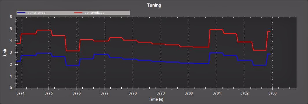
18ms 22uF
lh6.googleusercontent.com/-wPUD … k_18ms.jpg
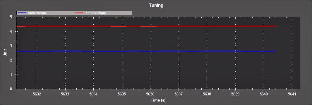
18ms 1522uF
lh6.googleusercontent.com/-zxRQ … 1522uF.jpg
Üritan nüüd veel ühest asjast aru saada, kas tuning graafiku uuenduse kiirus on 3-4Hz või on see ultrahelianduri väljundi tegelik sagedus. Kalku järgi peaks olema 55Hz[/quote]
Made a new filter. Now I’m using 100uF ceramic capacitor and a 470 ohm resistor, signal is fast.
My conclusion for the HC-SR04:
It will work and is fast, accurate enough if you are measuring distances between 0 and 1m. If you would like to measure bigger distances it will be slow ~0,3 s reaction time and not so accurate. If you were using an arduino with a hardware analog output it probably would be accurate and fast enough. When using PWM for analog you will have to chose your distance and calibrate it to that. Biggest problems come from code update speed and filter that needs to be non constant to give accurate and fast reading for the whole range from 0 to 4 m. Filter with constant values does not work the whole range.
I would have to say HC-SR04 works almost in a stable way from 0 to 2,5m. I reduced the output value even further, 1m is sufficient for me, although APM sees max 1,5m and scaling is good. Bigger distances are not stable.
To make scaling simpler and to get rid of the unstable range I added some lines to the code:
[code]int a = map(cm, 0, MAX_DISTANCE, 0, 255);
if (a > 100)
a = 100;
if (a <= 5)
a = 0;
analogWrite(pwmPins[sensor], a );[/code]
Full code:
#include <NewPing.h>

#define SONAR_NUM      2
#define MAX_DISTANCE 250
#define PING_INTERVAL 50

unsigned long pingTimer[SONAR_NUM];
uint8_t currentSensor = 0;

NewPing sonar[SONAR_NUM] = {  // trigger pin, echo pin, max distance
  NewPing(5, 6, MAX_DISTANCE),
  NewPing(7, 8, MAX_DISTANCE)
  };

int pwmPins[SONAR_NUM] = {
  10, 11 };

void setup()
{
  Serial.begin(19200);
  pingTimer[0] = millis() + 75;
  for (uint8_t i = 1; i < SONAR_NUM; i++)
    pingTimer[i] = pingTimer[i - 1] + PING_INTERVAL;
}

void loop()
{
  for (uint8_t i = 0; i < SONAR_NUM; i++) {
    if (millis() >= pingTimer[i]) {
      pingTimer[i] += PING_INTERVAL * SONAR_NUM;
      sonar[currentSensor].timer_stop();
      currentSensor = i;
      sonar[currentSensor].ping_timer(echoCheck);
    }
  }

    // Other code that *DOESN'T* analyze ping results can go here.
}

void echoCheck()
{
  if (sonar[currentSensor].check_timer())
    pingResult(currentSensor, sonar[currentSensor].ping_result / US_ROUNDTRIP_CM);
}

void pingResult(uint8_t sensor, int cm)
{

  int a = map(cm, 0, MAX_DISTANCE, 0, 255);

  if (a > 100)
    a = 100;

  if (a <= 5)
    a = 0;

  analogWrite(pwmPins[sensor], a );

  Serial.print("Andur ");
  Serial.print(sensor); // print sensor number accessed
  Serial.print(" = "); // = märk
  //        see prindib reavahetuse ka lõppu, väljund hüppab järgmisele reale
  Serial.print(a); // sensor distance value
  //        see prindib reavahetuse ka lõppu, väljund hüppab järgmisele reale
  Serial.println(" cm "); // cm

}
2 Likes
Signal is actually nice now. For small distances it works
lh3.googleusercontent.com/-n7cp … Bsonar.JPG
NB! Remove Serial print related stuff from the code, it makes the PWM to lose sync at some points in time.
Hi Riff,
What is the configuration of cables between arduino and APM ?
OutPut pin number?
that analog out put pin number
Hi,
I don’t remember that well but in the code it should be pin 10 and 11 (Arduino Nano board), I had 2 sensors.
int pwmPins[SONAR_NUM] = {
10, 11 };
I have been away from Arduino and Rover for some time now, sorry for no reply to some people.
I wanted to add some info, when building an filter that manipulates fast signals (in this case digital to “semi” analog), always use a ceramic capacitor, because the LOW ESR dielectric capacitors will not handle fast signals, they are unable to react/function fast enough.