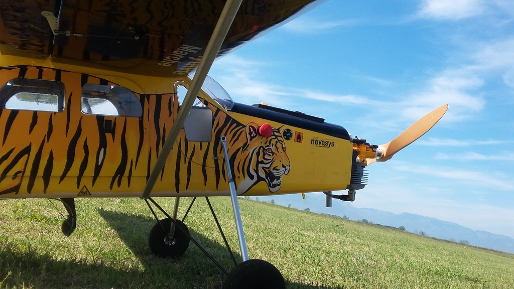
The Pilatus Porter airframe, on which the UnATRaP was based, comes with wing struts intended to share the load from the wing boom, in large positive and negative G-loads.
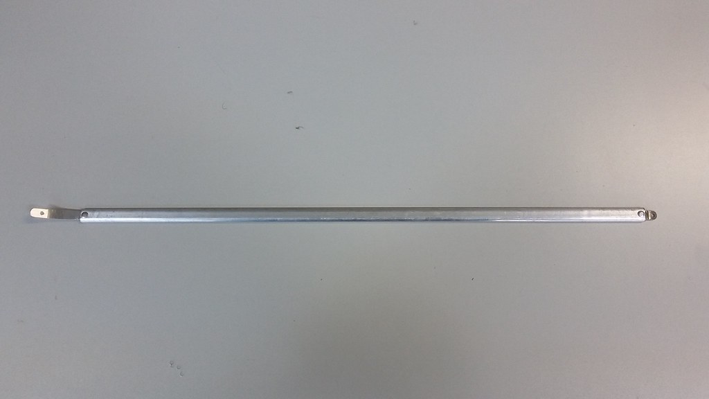
Each wing strut consists of a flattened aluminium-like tube with a soft metal strip and a flat chain link, riveted on each end, in a soft wood sandwich.
It has two mount points, one under the fuselage and one mid-wing on the underside. It is fastened with M3 screws, screwed against blind nuts.
We knew from online reports that this was a weak structural point. The wooden pieces, supporting the riveted sandwich were known to crack and wither away, leaving the flat chain link loose and prone to dislocation. We poured amounts of CA glue to harden the wood and hoped for the best.
Besides, we were not convinced that the wings needed extra support, since many 3D planes only rely on the wing boom to keep the wings from clipping.
However, from the very first flight tests, it became apparent that this structural part was indeed under stress:
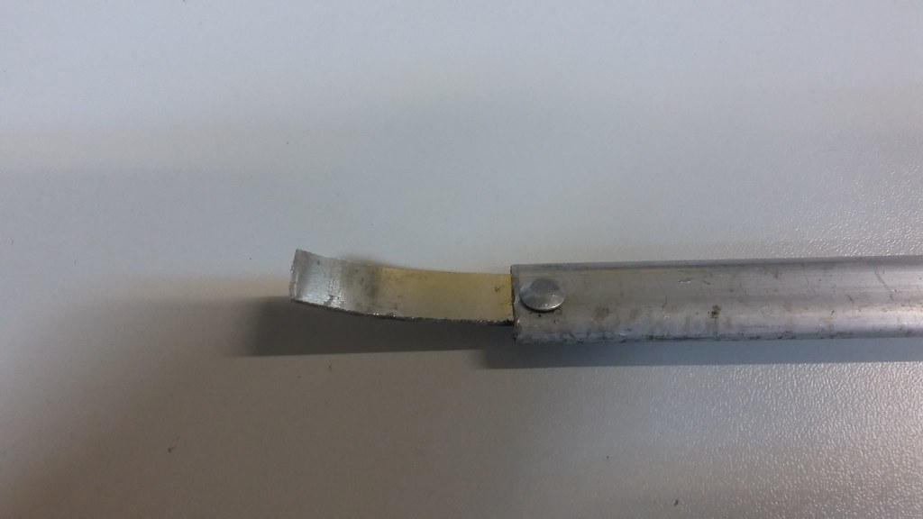
Under level flight the wings didn’t flex noticeably and the strut didn’t compress. But during aggressive manoeuvres the bottom metal strip would contract and extend, getting weaker with each cycle.
Eventually, the inevitable happened:
more than once:
The fault point was always the same:
So the next question was - do we want to replace this part? If we intended to do cruising flights exclusively, we might have not worried about it. But a lot of excitation manoeuvres for system identification were in schedule, so we didn’t want to test our luck. Besides, if the strut flexed, that meant that some deflection (unwanted or otherwise) did exist.
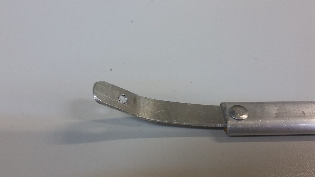
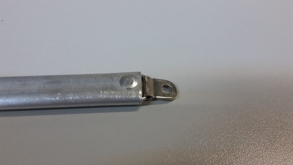
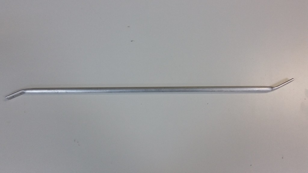
After some external input, we went for a 12mm (10ID, 12OD) aluminium tube, which we cut to length, heated with a blowtorch, pressed and bent on a vise. Preheating was necessary, because the tube would crack if we pressed it while cool.
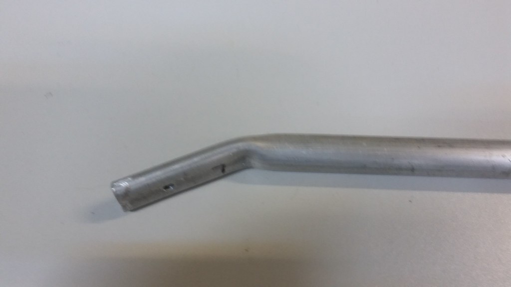
The result was more than pleasing. It might weigh a bit more, but it was right on the CG, so we didn’t worry too much about it.
This concludes this part of the UnATRaP blog series. If you have comments or recommendations, please let me know. Until next time!
Previous article: Part 5: Hardpoints and Mounts
Next article: Part 7: Main Landing Gear
EDIT: I forgot to mention this excellent link to the wing strut modification misokosik has done on his Porter. Clearly superior but definitely a greater investment in time that what we were prepared to make.