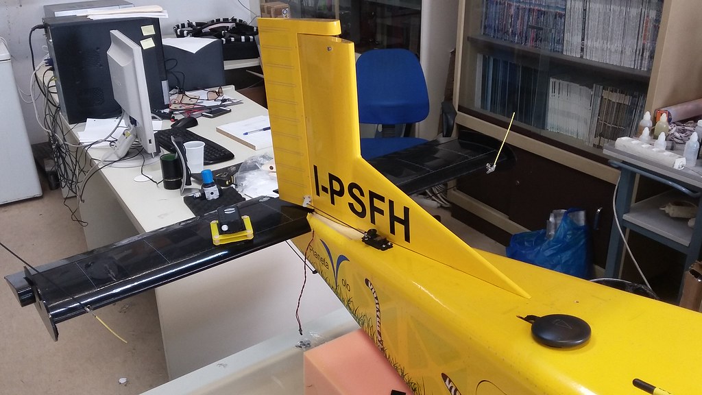
The Pilatus Porter is a taildragger design, obviously. And even though planes are meant to be on the air most of the time, where wheels aren’t used, there is still that pesky takeoff and landing part. As a result, we should have an, at least basically, functional tail wheel system, to control heading on the ground.
Unfortunately, this is one of the major weak points of the VQ model. A series of bad design choices make the tail wheel effectively useless.
Rudder Assembly
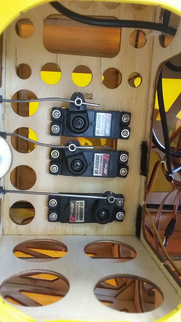
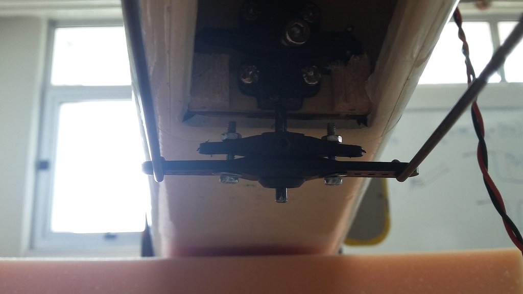
First of all, there is a single servo controlling both the rudder and the tail wheel (bottom one on the picture). Okay, this is to be expected for a 5-channel plane, so I won’t complain too much about it.
But then, the pushrod coming of the servo is led to an internal control arm which is held against a vertical wall (photo). A vertical axis is secured onto this arm. To the top, it drives the rudder assembly with a 90-degree bend. To the bottom, it is fastened to another external control arm, driving the tail gear.
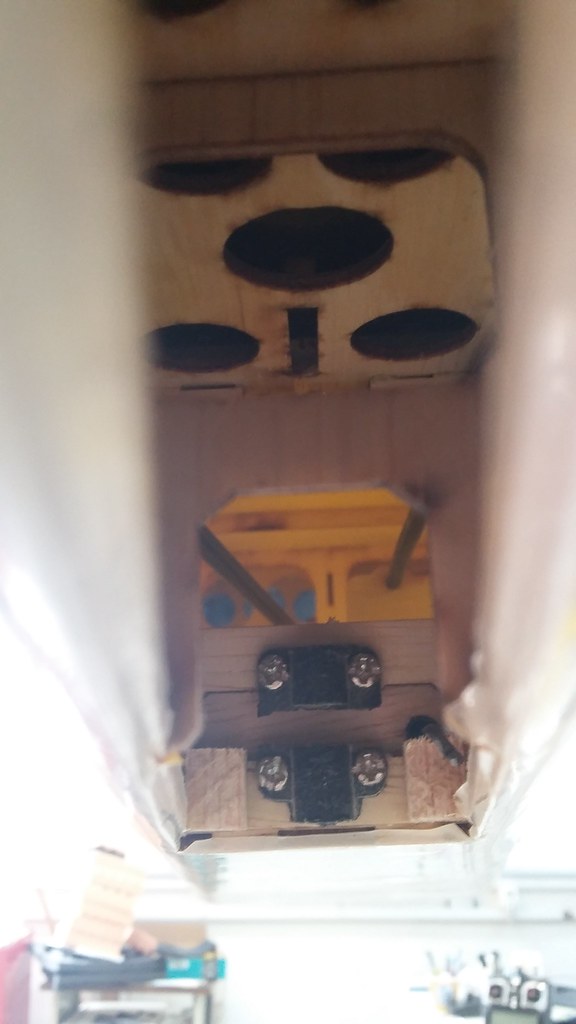
The internal control arm has barely any room to pivot, seriously limiting the available throw of the servo. Even worse, the throw isn’t the same in both directions. We tried to extend the throw by drilling and filing the vertical wall, giving some room for the internal control arm.
Still, that meant that both the rudder and the tail wheel whould be linked mechanically and that wasn’t something we were happy about. Bumps caused by rough terrain could wear out and damage the internal linkages through the tail gear, exposing the rudder control to danger of failure. Not a good thing to happen during take off: the Porter has such a wide side area that is impossible to land without a rudder.
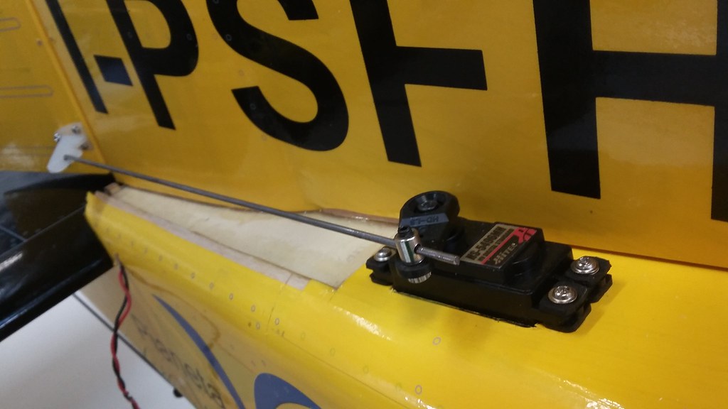
So, we decided to add another channel and use a separate servo to control the rudder. Taking after other modifications we found online, we installed a servo externally, on top of the tail back section. The vertical internal link was cut with a Dremmel tool to separate the rudder and the tailwheel. The independent control channel is very welcome, but at a cost: The extra 50 or so grams of weight that far back, mean another 100g of ballast on the front, to balance the plane, totalling an increase of over 150g to the takeoff weight.
Tail Wheel Assembly
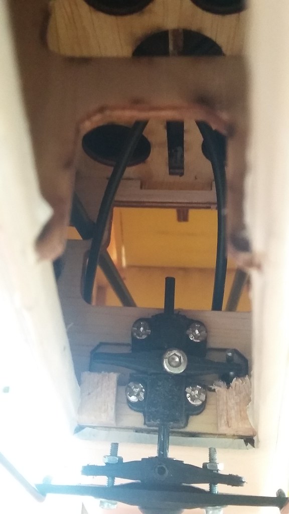
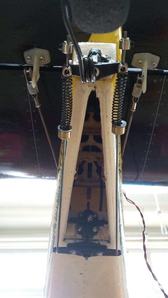
Next, we turned our attention to the tail wheel. First of all, since we usually fly over somewhat uneven and rough terrain, we decided we wanted to introduce some mechanical springiness to the wheel, to avoid shocks which could affect the already flimsy assembly. We went with two compressed double springs inserted over the tail wheel final control rods. On the front end, they are held by a fixed collar and a washer. On the back they push on the EZ connectors, which are not tightened, to allow for “play”. The collars on the back end of the linkages are there to prevent them from sliding out of the EZ connectors, at a worst case scenario.
The good news is that we haven’t had any damage on the rear landing gear, using this assembly. The bad news is that control authority of the heading while on ground is weak, at best.
We tried to extend the tail wheel throw by installing a larger driving control arm but it hasn’t made much of a difference.
In the future, we will try with either much stiffer springs or we will remove them and fix the control links on the EZ connectors, whatever the consequences.
This concludes this part of the UnATRaP blog series. If you have comments or recommendations, please let me know. Until next time!
Previous article: Part 2: Fuselage Front Section
Next article: Part 4: Fuel Tank