at I am thinking with input from Paul, Tridge and Randy.
I would be interested to know how much this will help the heli controller design having the feed forward term included. ArduCopter V4 Attitude PIDs.pdf (56.0 KB)
Hi Leonard,
Thanks for the information on your plans for the PID controller! It’s great to hear that you had plans on incorporating a notch filter. Based on my recent investigation with notch filters and Markus’ difficulty with it in the pitch axis, would it be possible to notch filter the gyro signal rather than the error. For low frequency instabilities(<4 hz), it might allow use of the notch and not affect the pilot input at that frequency, just the feedback.
I believe the Trad Heli firmware already has this capability. It is the only way we can get sufficient control power since the P term cannot be raised due to instabilities.
Thanks again for the info. Please let me know if there anything I can do to help. This will be a HUGE improvement for Trad Heli users.
Yes, the notch filter is only in the gyro signal, not the error signal so if I understand you correctly, that is what you are asking for.
As for the feed forward, I understand that heli has this already. What I am hoping to do is make sure the new PID loop design allows heli to simplify their controller design.
Thanks for the feedback, any other ideas or suggestions?
We are hoping that this will go into the next release but we need contributions from a number of people to make this happen.
The full story is we want to sync the rate loops to the gyro read and increase the maximum rate to 1kHz. For heli this will need to be able to be reduced to 125Hz or something like that probably but that won’t be a problem. The slew filter at the front helps us deal with the problem of updating the rate request at a lower frequency than out rate loop is calculated. So the process will be:
gyro read (8kHz) with an averaging filter down to 1kHz
rate loop calculation at 1kHz
EKF update at 200Hz to 500Hz
The rest
So once that is in I hope that we can simplify the Heli PID loop. I think the only thing we don’t have is the leaky I term but I will need to understand that before considering how or if we include it.
So are you increasing the speed of the fast loop? What is the driver for that?
Are you reducing the speed for heli because servos are being driven instead of motors?
Have you decided on the notch filter? 2nd order? Will the user be able to adjust the depth and width? I am not that well versed with filters. I went through a little trial and error with the parameter that adjusts depth and width. I chose to make it a little deeper to attenuate the instability as much as possible but the trade off, at least with the digital filter I used, was the width was bigger. How do you plan to determine this?
I had not played much with the leaky I feature currently implemented in the Heli firmware. I had tried my own implementation based on the logic used for the hover roll trim feature of the heli firmware. I ramped in the I term over 5 seconds. The code is exactly like the hover roll trim but adjusted to ramp over 5 seconds rather than 1 second. I don’t think the hover roll trim logic works well for subsequent landings and takeoffs unless you were to disarm then arm each time. My only other suggestion would be to trigger the leaky I term on a Weight on Wheels (WOW) switch. It is the only way to truly know that the aircraft is on the ground or in the air. I realize introduces a number of issues from requiring each user to mount this on their aircraft to reliability and mounting of the switch and of course programming it.
By the way I found an issue the hover roll trim code. When the scalar term is calculated, the equation is type casted as a float but there is a division by an integer in the equation which was not type casted as a float and the hover roll trim scalar ramps in quicker than 1 second. Once I type casted the integer in the denominator as a float, the hover roll trim ramped in at 1 second.
Leonard,
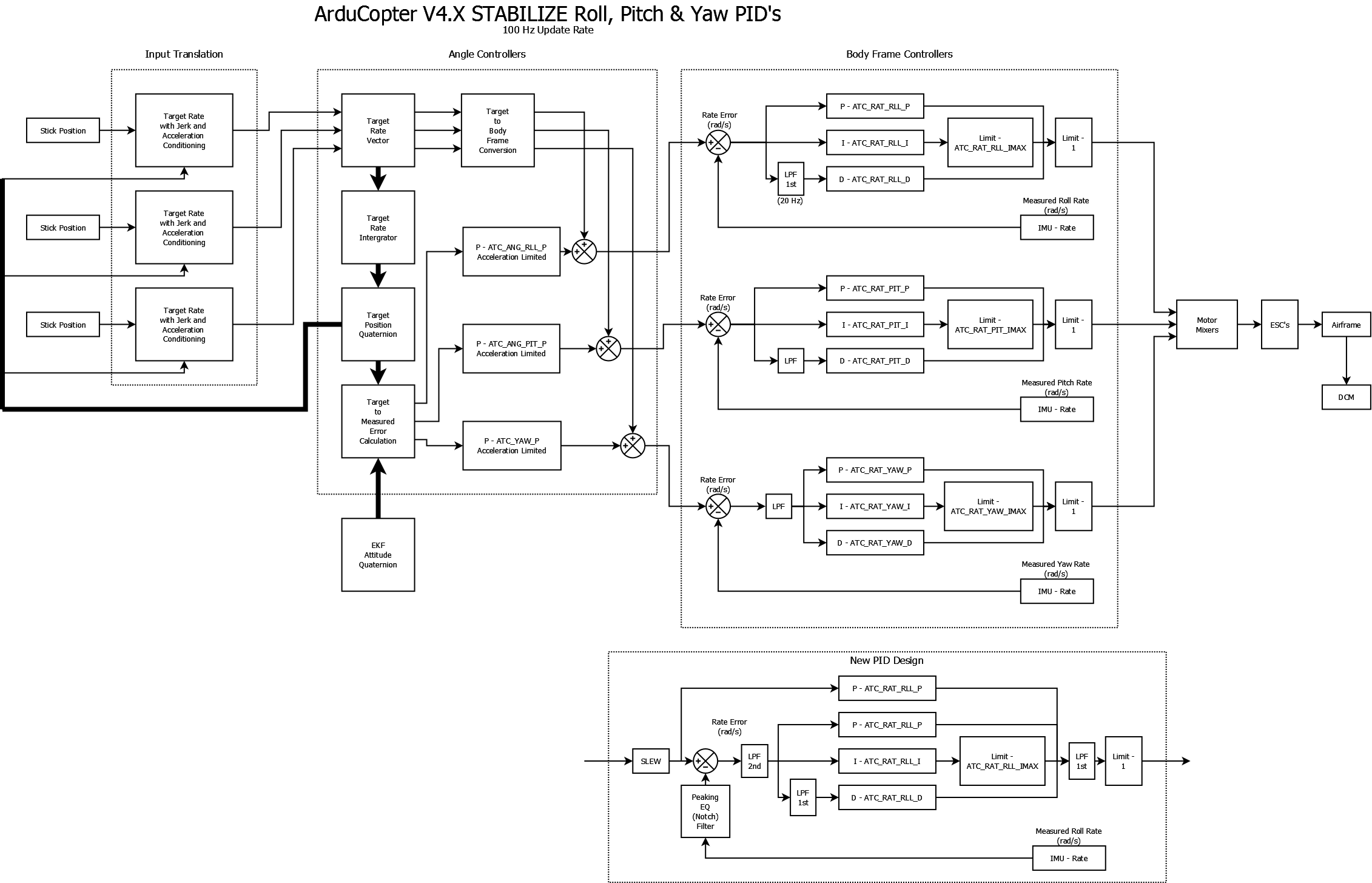
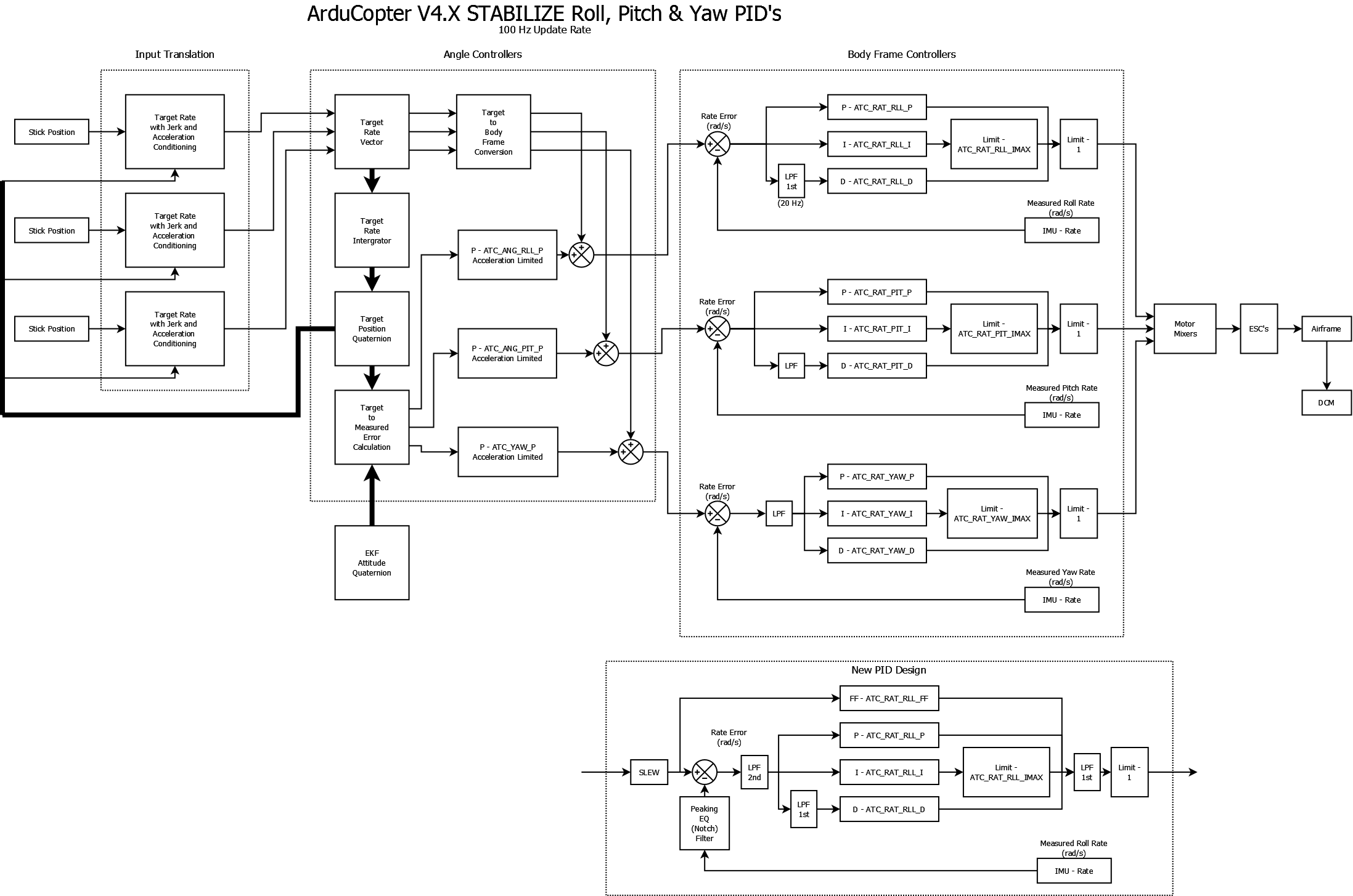
I just looked at your control law diagram more closely and noticed the New PID design at the bottom. This answered one of my previous questions. However I have a few more regarding the design. I like the Notch where it is placed (like we discussed). Why do you have an LPF right before and after the PID? What are you guarding against? I like having the 2nd order LPF prior but I would recommend putting it directly after the Notch on the gyro signal only. Also recommend leaving the LPF on the D term and remove the LPF after the PID. Is there some noise on the target rate signal that you are concerned. I know in the calculation of the target rate, AHRS attitudes are used which could introduce noise. Maybe consider a separate LPF on the FF like it was in the TradHeli code and remove the LPF after the PID. See below
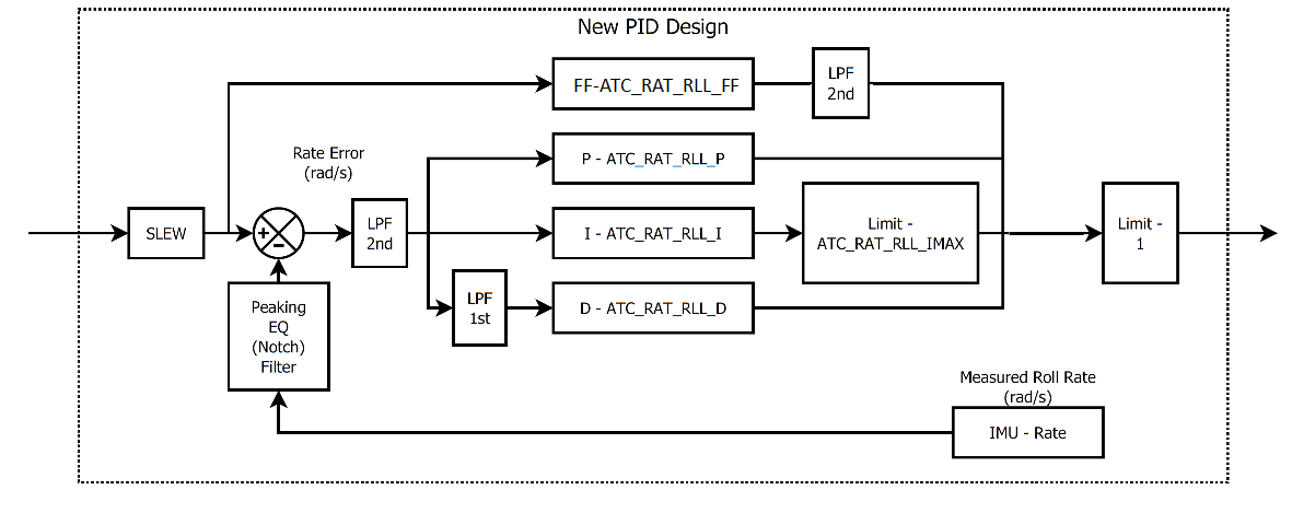
On a separate note, I like the fact that Trad Heli code has separate gains for the FF and P. This shows that they would be the same gain. Because of our instabilities which I think the notch and LPFs will help, I still think there will be cases where you may need more or less FF than the P. I also reflected this change in the picture above.
It is essential to have separate gains for FF and P in the current code !
Using an external FBL-unit you set all ATC_RAT_[PIT,RLL,YAW][P,I,D] = 0 and you must have ATC_RAT[PIT,RLL,YAW]_FF > 0 to be able to control the helicopter in any stabilized mode.
There is a problem in the setup as well and maybe it can be solved by something like this:
if H_FLYBAR_MODE == 1 && H_SWASH_TYPE == 1 then
// do not change user settings for H_SV[1,2,3][MIN,TRIM,MAX]
// using an external FBL-unit user must provide correct TRIM,
// otherwise FBL-unit sees stick input
// and MIN and MAX should provide correct endpoints for the FBL-unit
→ it works for H_SV4[MIN,TRIM,MAX], we just need the same for H_SV[1,2,3]
else
// current code overwrites user settings
H_SV1_MIN = 1000; H_SV1_TRIM = 1500; H_SV1_MAX = 2000;
H_SV2_MIN = 1000; H_SV2_TRIM = 1500; H_SV2_MAX = 2000;
H_SV3_MIN = 1000; H_SV3_TRIM = 1500; H_SV3_MAX = 2000;
end if
Yeh, the feed forward was a mistake, it was supposed to be labeled FF not P. So I agree, the feedforward definatly needs to have a separate parameter!!
So the filters have been placed where they are because we need:
a second order filter on the gyro input to reduce high frequency noise,
a filter on the request to reduce noise caused by the lower update rate of the rate request,
a first order filter on the D term only,
a first order filter on the P term for yaw in multirotors
a filter on the FF
a notch on the gyro measurement
So I have combined 1 and 2 by placing the second order filter on the error output. 3 is a separate filter. I have combined 4 and 5 as an output filter and made it first order. 6 is a separate notch filter on the gyro only. This filter is currently a second order notch filter defined by three variables, centre frequency, bandwidth, and depth. So you won’t have the problem with the width of the filter changing when you increase or decrease the depth of the filter.
Tridge has replaced the PX4 drivers making them much more efficient and that has let us increase the update rate.
Yes, we don’t necessarily need to run the loops as fast for heli. However, there may be advantages in keeping the rate at 1 kHz to let the filters remove noise as well as possible. The problem here is that by reducing the rate the aliasing problem gets worse. I am leaning on the side of running the rate loop at 1 kHz but only outputting at the requested servo update rate.
On the leaky I term. My understanding of this is it is there to limit the I term buildup when landed or landing and taking off. We can probably achieve the same thing by simply reducing the I_Max to a user defined level over a 5 second period. My problem with the leaky I term is it is hard coded and the behaviour changes based on the value of I. I suspect my suggestion would make things more predictable and constant with different tunes.
There is a noticeable difference in running a helicopter tail servo at 333 Hz or at 125 Hz (if you tune the tail using 333 Hz and than reduce it to 125 Hz the tail will oscillate).
Usually the swash servos are slower than the tail servo. In the moment the RC_SPEED parameter doesn’t allow to use the potential of the tail servo unless the swash servos have the same speed. Having RC_SPEED to set the swash servos speed and H_SPEED_TAIL for the tail servo would be perfect.
@ender-chen it depends on the cause of the vibrations. This technique is really to address aircraft/flight control system instabilities. The idea is that the control is being influenced by the aircraft movement (oscillation, vibration…) and essentially they feed on each other. If the vibration is caused by a propeller imbalance or, in the case of helicopters, rotor track and balance, then this technique will not work. Quadcopters also see instabilities that occur as the P gain is increased in the controller. From my understanding, these instabilities occur at P gains above 0.3 or so, which allows sufficient control response. Therefore these techniques are not required for quadcopters.
These techniques are applicable to multirotors carrying gimbals that happen to have a mechanical resonance in the control bandwidth or large multi rotors with flexible frames. There is also potential benefits for quad plane with flexible wing mounting and large noise levels coming from a combustion engine. So this work benefits all these frames.
@Leonardthall Thanks for the feedback. The notch filter design sound like it will be very useful.
My biggest concern is the filter after the PID. As you are probably aware, more filters means more phase loss. I’m assuming many of these will have fairly high cutoff frequencies (<10hz) so that will limit the impact of phase loss on the handling qualities. How many will have a user settable cutoff frequency?
So what’s the issue with yaw in multirotors? instability similar to helis in pitch/roll? Would this be set to a lower frequency (<10hz)? Why can’t it be addressed with the 2nd order filter on the error signal prior to the PID? I apologize for the 20 questions. I’m sure the developers have put a lot of thought into this. Just want to understand the design and how it impacts TradHeli firmware. Thanks for indulging me.
The current AC FW continuous update, Acro mode control, only applies to mechanical Flybar helicopter; and for the Flybarless helicopter, the Acro mode control is very bad.
I’m sorry I have not had time to test your 3.3.3 FW with a notch filter. I will have time and space in a few days and I will step up to test and give you a feel for the test!
Fredrik,
I should have given you credit. My work on the compound Heli frame was mostly based on your pull request. You developed that on AC 3.2.1 right? I moved it into AC3.3.3. I don’t have intentions on flying mine in auto mode but I’ll have to look at your implementation to tie thrust to the desired pitch.
Thanks again!
Bill
After looking at your pull request, you did have it in 3.3. I think I was not familiar with how to use github to pull your changes into my branch. So I did it manually. Nonetheless great work!
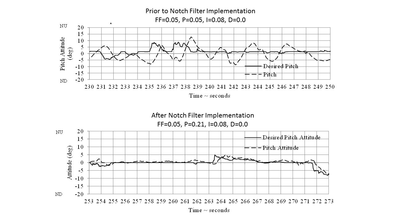
Update: Recently flew the X-3 with the AC 3.3.3 software modified with the notch filter. I was able to achieve forward flight up to 35 kts. The aircraft handled very nicely. Here is a plot showing a before and after of pitch attitude maintenance.
The top plot shows a flight conducted before I implemented the notch filter. Notice that the pitch attitude is varying 8-10 deg from the desired pitch attitude. The lower plot shows the flight I recently conducted with the notch filter implemented and the PID gains tuned. The PID controller was able to hold the pitch attitude to within a couple of degrees. This will provide excellent pitch maintenance as I expand out the forward flight envelope.