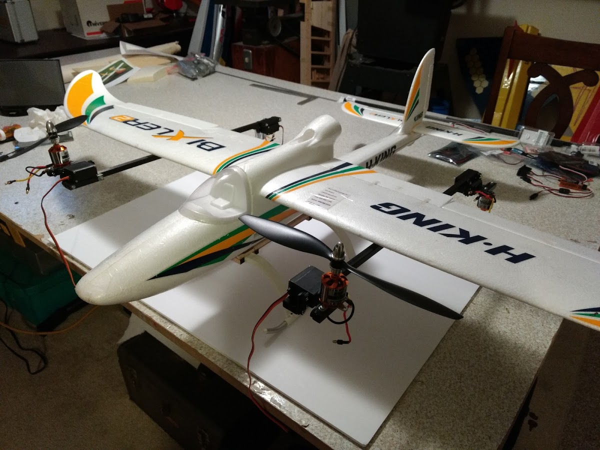
Hello all. I have a 3dr mini pixhawk with plane 3.8. I am close to completing the hardware setup on a bixler quad (tiltrotor) plane using H configuration. The two forward motors face upward during hover, the two rear motors face downward (pusher). This way the forward flight transition has all motors working together to provide the thrust to push the airplane forward. I am not sure that the pixhawk supports this configuration for a tilt rotor (as opposed to all 4 motors facing upwards). Can anyone confirm this for me? If you have experience or knowledge on this setup, all comments are appreciated! Thanks in advance.
Hi Tim,
It sounds like a fun project so please post some photos!
Your setup falls into a Tilt-Rotor Type where it is a tilt-quadplane with all four motors tilting. It doesn’t matter if your rear motors are facing upward or downward, only that you rotate them to add forward momentum.
I would set the Q_TILT_TYPE set to Continuous (or 0). Use the normal motor tilt SERVO11_FUNCTION=41 and set the servo mechanics so that they tilt in the proper manner. Perhaps a servo reverser may be needed for the rear tilt servo.
Good luck!
Thanks for the reassuring update, Greg! I will upload a photo of the plane in a few days. I am in the process of mounting the carbon fiber motor arms to the wing so it will be ready for photos shortly. Still need to decide on a lightweight landing gear and of course finish all the wiring and programming. BTW, I did need a reverser for two of the servos, you are correct.
Tim
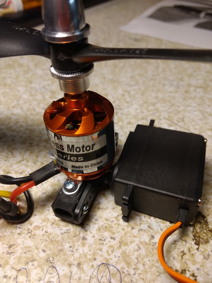
Nice! I would interested in seeing some details on your motor-to-servo mount and your servo-to-boom mount.
Since the Bixler doesn’t need much forward thrust to stay in the air using the normal pusher power system, it will be interesting to see how it flies with four props.
I hope those servos are full metal gear and have dual ball bearings on the output shaft. You are putting a lot of force and vibration into the output shaft by directly mounting the motor to it.
Also make sure the boom to wing mount is sturdy, because the motors are creating a momentum through the offset motor mount.
Motor/servo attachment. Thanks for the comments about the servo and the mounts. Biggest issue I have is with the centering on the digital servos. They center well, but not consistently at the same point and the splines do not have enough latitude to get a consistent centering point for all four servos. Would a servo programmer help with this?
It looks solid enough. What is the servo number?
You should be able to get good information on the performance from your hover testing.
Good luck!
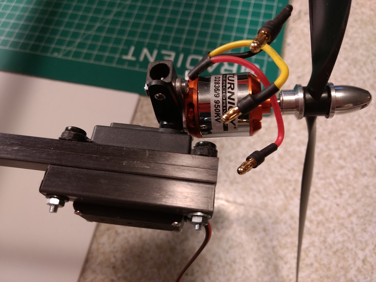
I got to make another comment. Those carbon fiber square booms you are using are pultruded. They have no interweaved fibers, only strands running in parallel from one end to the other and only held together by the resin. While they are great to take bending (to some degree) or pulling forces, they are not great at resisting torsion. Your way of mounting the motors introduces torsion into the booms. I would recommend checking the booms frequently, testing if one is softer than the others and looking for cracks. I used those booms on one of my bash around copters and one boom eventually became so soft, it allowed the motor to be twisted 15° left and right without much force. And those booms where only 20cm long. They also like to split at the seam, where the two halfs were glued together.
Servos are MG996R Digital Metal Gear. Thanks for your comments.
Hi Tim,
interesting construction. Some hints from our tri-tiltrotor experience:
I would choose an X-frame logic instead of H-frame logic, so that the torque of the propellers during forward-tranistion counteracts against disturbances at the roll axis. See: Tiltrotor support for plane and Tiltrotor support for plane
For the tiltservos you should each use a separate output (function 41)
Dont forget to set:
Q_ASSIST_SPEED 0 (tilted Motors cant help prevent stalling)
Q_TRANSITION_MS 0
Adjust the following parameters to your individual plane characteristics:
Q_TILT_MAX (Max. tiltangel while accelerating from hover to planflight and waiting, that FBWA_MIN will be reached)
Q_TILT_RATE_DN , Q_TILT_RATE_UP (degrees/second)
ARSPD_FBW_MIN xx (m/s, at thist airspeed the tiltable motors turns immediatly to plane mode and should be a little bit above stallspeed )
Be carefull: Do not accidentally switch directly from QHOVER to MANUAL MODE (instead FBWA) without enough speed or height above ground
Tiltrotor support for plane
Curious about your progress, good luck
Rolf
Rolf, thank you so much for your suggestions! Not sure what you mean about separate output for tilt servos. Do you mean each individual servo should be on its own channel? I had planned to use a combination of y-cables and a servo reverser to connect them all to the same channel (channel 11 was the indicated channel for doing this). I will definitely look into the x-frame logic; h-frame just seemed natural as that’s how the setup looks, but I can see that the physical setup doesn’t have much to do with that setting.
I am not fully understanding the modes, I guess I need fwba for the forward flight setting and what do you suggest for the hover mode? I can see where manual mode would not be a good thing!
Yes, this allows you to adjust each tiltservo precisely (SERVOxx_MIN/MAX/REVERSED ).
I suggest first to test QStabilize and Qhover flights like a copter. Then - without props on the bench- first test correct aileron/rudder/elevator moving in manual AND FBWA mode before real flight.
If you use an airspeedsensor, make sure it is calibrated correctly.
Regards Rolf
Thanks, Rolf! If I understand correctly, this will allow me to adjust for centering differences among the four tilt servos. I truly appreciate everyone’s input into this discussion.
Tim
New question. I have been reading about powering the pixhawk servo rail as I need to power four flight servos (rudder, elevator and two ailerons) in addition to the four tilt servos. Can I do this with a 2000 mah nimh pack connected like another servo to the output rail and if so, I don’t need the zener diode, right? I am thinking it’s probably not a good thing to use one of the ESC’s BEC to power the rail, as everything would ultimately get its source from the lipo. Your opinions are appreciated, especially as I get closer to completion on this.
Thanks - Tim
By the way, the 2000 mah pack is 4.8 volt. I’m guessing a 6 volt pack requires the zener diode.
Adding another battery means adding another point of failure, not redundancy. The lipo is monitored through the power module. You and the FC will know when it is empty and then failsafe kicks in or you decide to land beforehand. How are you going to know what the state of the nimh battery is? Better add a standalone BEC connected to the main lipo, with enough current rating plus a bit headroom to supply all your servos. Test it on the ground by moving all the servos and see if it drops out, before the first flight.
Thanks. I do appreciate your comments along with those who continue to show their support.
Initial testing of tilt-rotor: