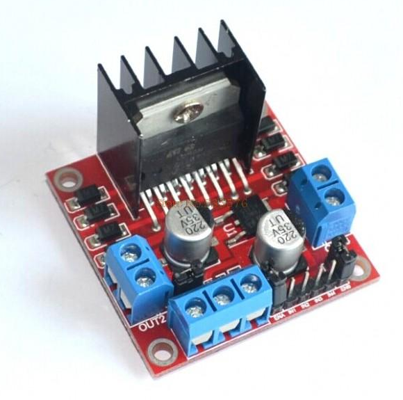
Hi all, as some of you might remember I was having a problem with my survey boat zig zagging terribly while carrying out a mission. At first I thought it was a Mission Planner parameter setting, but it turned out to be the little L298N H-Bridge failing due to excessive heat. This was caused by me upgrading the outboard motor to a Suzuki 2.5hp four stroke which turns out to have a LOT more drag on the pivot (steering) column. This drag put extra stress on the little 2A H-Bridge causing it to fail intermittently.
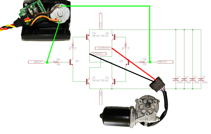
The solution was to upgrade the H-Bridge to a 10A H-Bridge, but being in South Africa, none are available locally so I built my own from a diagram on-line and connected as follows. This unfortunately puts it onto a DEAD SHORT condition.
This circuit requires that Input1 and Input2 are not high at the same time or it will burn out. The original design used a decoder chip to allow only one side to be active at a time. A 74139 decoder was used shown on this site: http://faq.solarbotics.net/BiomechMotorBridges.html
Also PWM can not be used to drive this circuit. Input1 is high motor is driven on that direction. Input2 is high and the motor is driven in the other direction.
Don’t know enough about your application. The bridge you built will work but only if both Inputs 1 and 2 are not driven high at the same time. The L298 had this built into it and other H-bridge configuration do as well.
In the past I used this board: https://www.parallax.com/product/28820 to drive two motors in a model army tank. You can also take a look at these devices as well: https://www.pololu.com/category/10/brushed-dc-motor-controllers
I would certainly recommend using an H-Bridge IC if you can, but if you can’t get them here is a circuit that will work using just transistors. This provides 2 inputs ( labelled on the left), one for direction of the motor and one to start and stop the motor (PWM). On the start stop input you can use a Pulse width modulated input.
I would also recommend getting some large diodes and connect them in reverse from the ground to the output each side and from outputs to the power supply. They prevent current spikes blowing the transistors
To a large extent this depends on how you are driving the direction and PWM inputs. Are you doing it manually or using a microcontroller or what? If a microcontroller, which one ?
So what your saying is that the PWM coming into the servo is controlling the direction of the servo motor. From there your feeding it into your bridge to power the bigger motor.
I think the problem with your design is that you don’t have a common ground. Also I don’t know if they apply a small amount of power to keep the motor in one place which will cause a problem for your bridge.
The problem is they are not using the same bridge type. Also since the small motor is still in the circuit it may be generating some kick back voltage which is not good for the bridge.
Ideally what your looking for is a large servo that excepts RC pwm input.
I would take @iseries advice and just order a large servo from somewhere like servo city, though there are quite a few power servos around from Hobbyking etc as well. I looked at the youtube video but I suspect these guys did a bit more than just hooking up a hobby servo output to get that working. I think they would have needed to hack the board a little as well.
By the way, did you know that you can use the both sets of outputs on the L298N to the same motor, just so long as you get everything wired up the right way including the inputs and the outputs. That gives you twice the current.