Hey there,
actually if i don’t want to use a apm current sensor would it be possible to wire up a small voltage divider and plug it into the voltage sensing port? has anyone done it?
I just dont want wo waste time and smoke anything.
TY
Hey there,
actually if i don’t want to use a apm current sensor would it be possible to wire up a small voltage divider and plug it into the voltage sensing port? has anyone done it?
I just dont want wo waste time and smoke anything.
TY
Hi Tommal,
The Power Module, does exactly that, ie has a voltage divider, applied to the voltage sensor terminal of the Pixhawk. I’ve modified that divider several times to get more accurate measurements. No problem
Good luck!
Thank you for the insight, looking at the schematics… 3.3 v is max? (corresponding to max voltage of the bat?) then it actually makes sense as the divider is most of the time 10 (6s).
Right,
In fact most power modules available, have a voltage divider of 1/10, with a resistance of 13.5Kohm and 1.5Kohm, respectively. I recommend that the 1.5 kohm resistor be connected as close as possible to the negative and positive 3.3v sensor, especially the negative. This is to avoid parasitic currents that alter the measurement with high currents in the motors.
Have a good time
Greetings,
I’m currently using a Matek XT60 PDB and a RceStar 4in1 ESC. Both have VBAT out that is the actual battery (4S) voltage.
The Pixracer Votage_Sense pin can receive at max 3.3V for sensing.
Can you please share the schematics of the voltage divider to use.
Thanks in advance
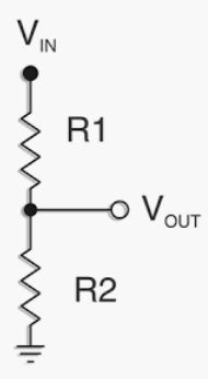
It’s not much of a schematic it’s 2 resistors. One (R1) being ~10k-15k and the other (R2) 1/10 the value of R1. Input to the PixRacer is from the center tap between the resistors. This ratio can go as low as 6:1.
Got it working
Thanks !