I don’t think this is true in a power sense but I think it does relate to the ability to measure phase. I will need to go into the maths more.
Sorry.
I don’t think this is true in a power sense but I think it does relate to the ability to measure phase. I will need to go into the maths more.
Sorry.
From what I know about spectral analysis coherence is the goodness of how well the output correlates with the input. Typically, any value above 0.6 is considered good correlation. A value of 1 indicates perfect correlation. I would imagine you know this. As for the accuracy of the phase, I guess good correlation doesn’t necessarily guarantee accurate phase estimation. I will still plan to get the data for the low frequency range. Hopefully that will shed some light on this.
You imagine wrong ![]()
I assume it is referring to magnitude-squared coherence though:
Coherence (signal processing) - Wikipedia
I will have to work through the maths to understand what it does and does not tell us. There is always something else to learn…
So True! I will be taking a course in January on CIFER. Part of it is learning how to determine a lower order system from the spectral analysis results.
I think the first chapter “Definition and Formulation” of the given link says it all about the coherence
I think you would want to find a means to have error bars on your data in the plots. E.g. in the data plots in the first post, the reason for the drop in coherence at low freq can IMHO be very clearly seen: from the Bode plots its clear it’s due to a drop in magntiude, and when you look into the data trace one clearly can see lots of noise in the first few cycles, and in fact a kind of a “jump” after ca. 6 cycles there it kind of “snaps in”.
Looking at this it could be maybe worthwhile to test if it could help to prepend the sweep by e.g. 10 cycles of constant frequency, in order to give the system some time and/or account for slow transients
great stuff btw
Just remember that the first time history plot contains only rout (the output of the attitude controller to the mixer) and the sweep signal that is included in rout. I did not include the rate response of the vehicle. So here is a time history of the Y6 frequency sweep in the roll axis (shown below).
The red is the output from the attitude controller to the mixer (rout) and the green is the roll rate response of the vehicle. The scale for Rout is on the left and the scale for the roll rate is on the right. I think it is pretty clear that the signal to noise is sufficient to support what is seen in the bode plot for 1 rad/s to 5 rad/s. Not only is the SNR good, it also shows that the aircraft is 180 deg out of phase with the input for the low freqency regime. I will go out and gather another sweep in the low frequency regime but I think the analysis is consistent with what is observed in the time history plot.
Thanks!
well, what I only wanted to mention is that in all plots there is a loss of coherence below ca 0.8 Hz or so … and I think it’s obvious why from looking at the data in the first few cycles (the last plot just reinforces it) … that’s all I wanted to mention 
No. I’m glad you wrote. It made me look at the trace and convince myself that the results from 1 to 5 rad/s are consistent with the time history. just a clarification. You mention 0.8 Hz. Did you mean Hz or Rad/s?
sorry, wasn’t careful: ca 0.8 rad/s
I don’t believe your magnitudes are “real” in that regime, and I think the hints are there
my 2 cents
I guess I wouldn’t expect good coherence below 1 rad/s since I didn’t run my sweep below 1 rad/s. Or are you speaking of frequencies above 1 rad/s where the coherence is good near 1?
ah … I missed that, sorry (I was assuing that the lowest shown frequency was the starting frequency)
so the plots below 1 rad/s are indeed not real, but for a trivial reason
I guess you want then to cut out the unreal parts in the plots
Sorry, didn’t think about that. I will do that for my future plots.
I am very confused about that low frequency phase.
Edit: I know what it is!!! It is propeller flapping torque. The aircraft is speeding up as it is tilted over and the propeller flapping torque is then being countered by the output of the rate loop.
In short for low frequencies you are characterising the relationship between propeller flapping torque or rate_out and airspeed. At higher frequencies airspeed can not build up and you are looking at the relationship between rate_out and rate.
Ok, everything is right in the world again now 
very impressive stuff!
Here is an update on the work that I’ve been doing. Just got back from a course on systems identification using a program called CIFER (Comprehensive Identification from Frequency Responses). I posted previously the pitch and roll frequency responses. I had also done frequency sweeps in the yaw axis but had not posted the results. I had the data with me and wanted to put what I had just learned to use. This course walked us through what was important about gathering the data (instrumentation, data consistency, frequency sweeps…), developing the bode plots that show the relationships between the important control inputs and outputs (states), and lastly how to develop a 6 degree of freedom model from the frequency response data. One thing that I learned/didn’t realize is how uncoupled multicopters are compared to helicopters. Helicopters become even more difficult to model going from a teetering rotor head to something that had geometric or effective offset (i.e. flap hinges displaced from the center of rotation or no flap hinges). So coming up with a model (set of transfer functions) that represent a multicopter is not too difficult. What remains to be seen is how scalable they would be to different multicopter size and configurations.
I used my frequency sweeps for the Y6 in roll and yaw to come up with a bare airframe model for the lateral/directional equations of motion. So you have 3 equations of motion for rigid body motion instead of the 6. SO the lateral directional equations are the lateral force, roll moment, and yaw moment equations.
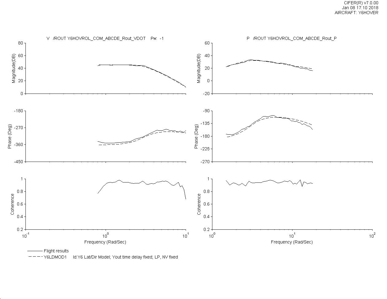
I used CIFER to fit the following frequency responses, roll rate § to Rout (roll mixer output), lateral acceleration (AY) to Rout (roll mixer output), body axis lateral translation velocity (V) to Rout (roll mixer output) and yaw rate ® to Yout (yaw mixer output). It also determined the modes of motion for the system and stability and control derivatives. Here are the plots of the frequency responses with the model laid over it.
first chart is V to Rout and P to Rout
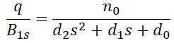
Generally the model is fitted for frequencies from 1.5 rad/s to 15-20 rad/s. It captures the unstable long term mode, the yaw short term mode, and the roll mode. There was no roll damping derivative which leads me to believe the roll mode is effectively acceleration command in the short term. Here are the transfer functions
So in order to develop a full 6 DOF model, I will need to do a sweep in the vertical axis with the collective (that’s throttle for the multi’s). Then I can use the same process. So this information could be used to develop better a better control system however these equations only apply to the Y6. So a lot more work would need to be done to understand how to build a generic model of a multicopter or helicopter and what physical attributes for that type of aircraft play into the eigenvalues or the stability and control derivatives.
Great work Bill!!!
Reopening this thread with some new data. @ChrisOlson and I were able to get some frequency response data on two fairly different helicopters. I think things are starting to make sense with regard to the RC helicopter frequency response. So here are the vehicles
Bill’s
Ergo .46 converted to electric
E-flite 700 heli motor
Castle Creation 80Amp 50VDC ESC
12s 5000mAh Lipo batteries
rotorspeed: 1800 RPM
blades: 600mm
rotorhead: Miniature Aircraft X-cell 30 2 bladed flybarless (I removed the flybar)
Dampers in rotor head are pretty soft.
weight: 10.5 lbs
swashplate servos: Futaba 3050 digital servos
Chris’ Heli
Synergy E5 stretch
I’m assuming it is running 626mm blades
Flybarless head with stiff dampers
low head speed 1550 rpm
high head speed 1700 rpm
I’ll let Chris fill in the rest. I’m sure his is a little lighter than mine.
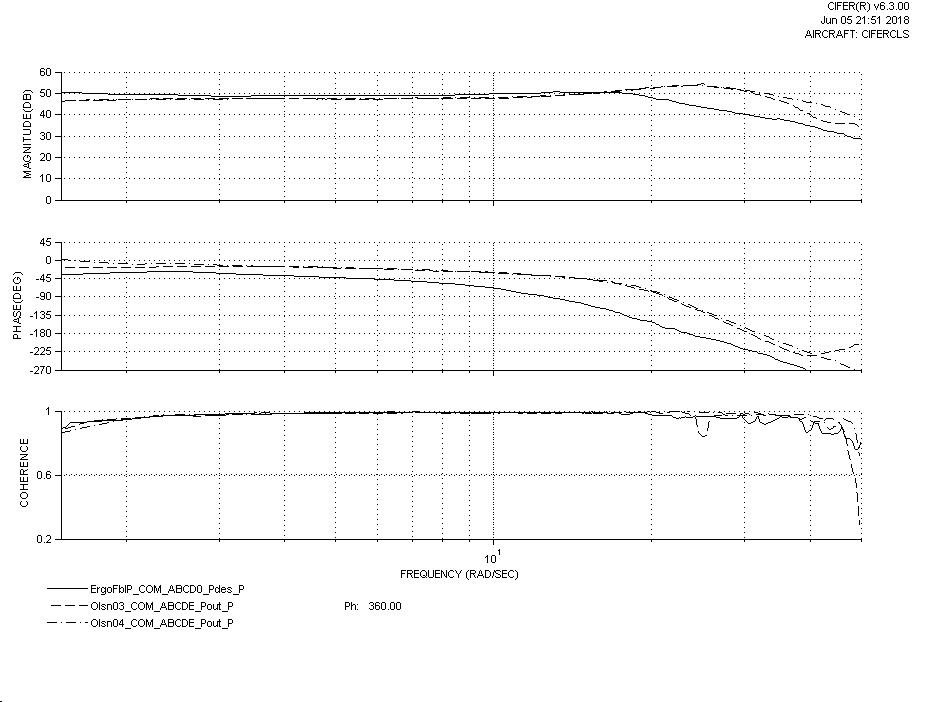
Here is the comparison of the two aircraft in pitch. This plot is a bode plot of pitch rate to pout which is the pitch command being sent to the mixer. I plotted coherence there for completeness but tried to trim the plot on the x axis to exclude regions where the coherence was poor.
ergo is labeled ergofbl
626 low headspeed is labeled olson03
626 high headspeed is labeled olson04
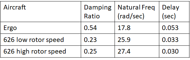
Yields the following data for the bode plot above
I will continue with the roll results at a later time.
This is soooo cool!!
That may be the resonance of the head dampers at about 25 Hz on the Olsen 03 04.
Sorry I have been offline, I have been crazy busy lately.
Chat soon!
This is 25 rad/sec not hz. So about 4 hz. I have believe we are seeing more lightly damped rigid body modes than the full scale Helis. Full scale helicopters with teetering rotors like the jet ranger (Bell 206) or the older H-1’s (also Bell product) can be modeled as a first order system for the roll and pitch rigid body modes. Even some of the lower geometric offset designs like the H-3. Geometric offset is the distance from the shaft to the flapping hinge. This helps increase the maneuverability of the aircraft. As the rotor system gets stiffer like in hingeless designs (i.e. Virtual flapping hinges) like the BO-105, the rotor response starts to couple with the body of the aircraft and the rigid body modes become second or higher order. Most full size helicopters have higher inertia rotor systems and thus the rigid body modes are fairly well damped (damping mainly coming from the rotor system).
So with model helicopters, the desire is highly maneuverable aircraft with good rotor response. So the rotor blades for the flybarless designs are lighter with less inertia and even though they are teetering rotor systems they have stiff dampeners that help drive up the natural freq. This means the rigid body modes are less damped and have higher natural frequencies.
So I’ve been reading Tischler’s book on helicopter system identification. Using the transfer function results, some rotor system characteristics can be determined. The rotor flapping time constant, natural frequency and control system delay. For Chris’ 626, it is 0.084 sec and for my ergo, it is 0.052 sec. seems odd that mine is quicker than chris’ which has the stiffer dampeners but they really impact the natural freq more than anything which is very obvious in this case. The Delay column in my previous post is the control system delay. You can see that my delay is much higher. I’m using digital servos but they are probably not as powerful as they should be.
So now the challenge is designing a control system that can better handle a lightly damped system. I think the current one does pretty well but maybe we can do better.
Regards,
Bill