I have tried it too but no luck so far.
The firmware for the Pixhakw 1 and Pixhawk 2.1 is the same and although there are differences in code in some places, this isn’t one of them. Please check if you aren’t mixing the connections.
In your previous answer you mentioned old external bus which you mean internal bus(according to website documentation).Am I right so far?
No, I mean external bus. Pixhawk 1 has an internal bus and an external bus, Pixhawk 2.1 has both buses on external ports. The driver for the displays only looks in the Pixhawk 1 external bus, which matches the one in the GPS 2 port in the Pixhawk 2.1 (according to documentation).
You are quite right about that but in documentation they have placed GPS 1 as external and GPS 2 as internal. Which it should be the other way round.I ll try that if it work.I ll let you know.
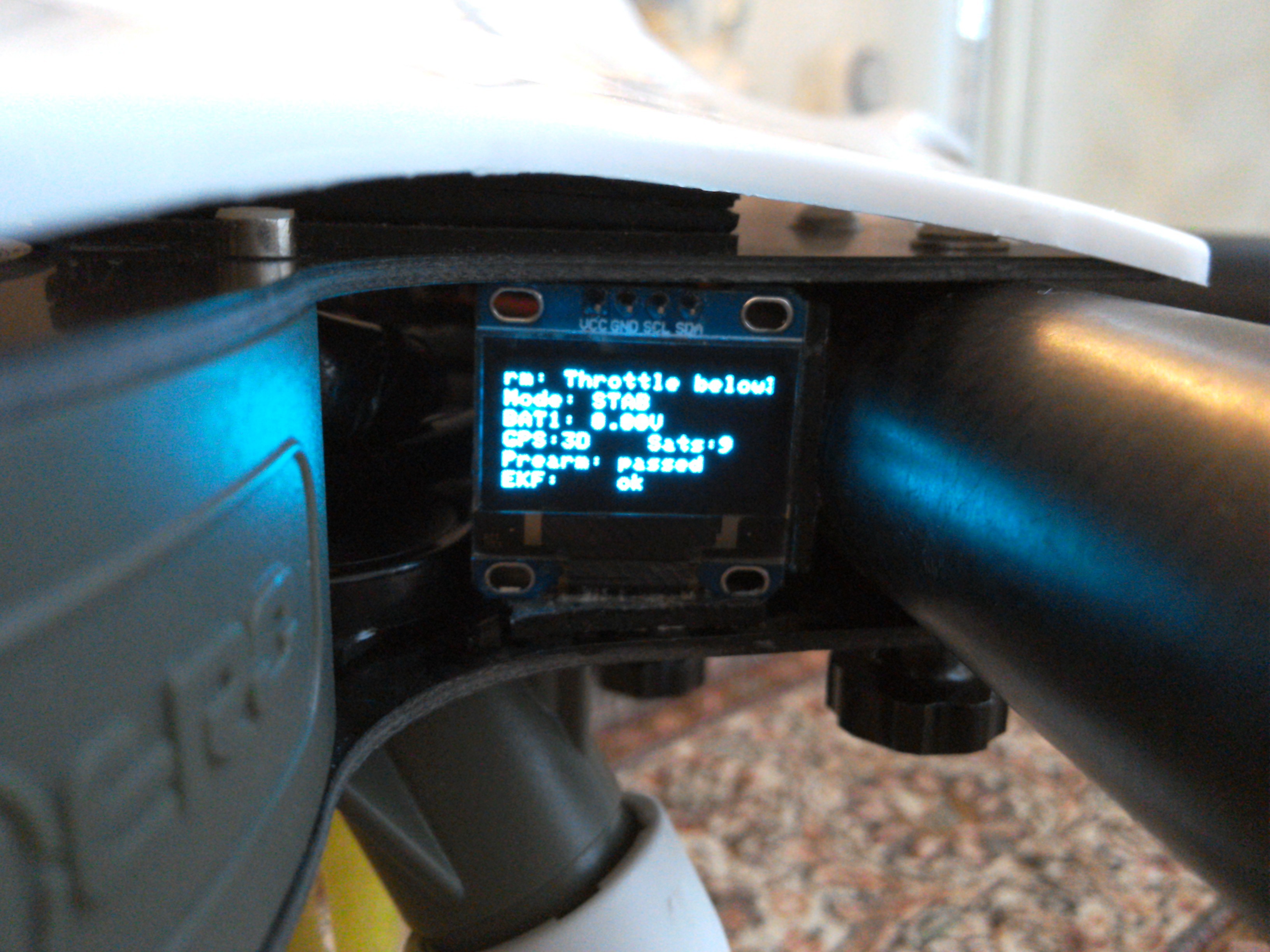
I have tried what you said and checked the wiring diagram in documentation and measured the output Voltage in both SCL and SDA and shows 3.27V through
USB connection. But still doesn’t show anything on Module.Some part of documentation info is misplaced and confusing.If you look at board diagram and the wiring connection to each port GPS 1and gps2 info are misplaced.I have the same display as RAWLIQUID has.He tried both gps1and 2 with no luck.It seems it works on gps1 as Christian Mauch has tested it.
https://m.facebook.com/groups/847946361954654?view=permalink&id=1215970931818860
So apparently my initial thought was correct:
- GPS1 has old external I2C bus
- GPS2 and I2C 2 ports have old internal bus
Page 17 of http://www.hex.aero/wp-content/uploads/2016/07/DRS_Pixhawk-2-17th-march-2016.pdf has the specs for the “UART GPS” port, please confirm you are connecting the right places.
Problem solved as you said .The connection should be on pin 1,4,5,8 of GPS 1 according to documentation.Thanks
It sounds to me like the silkscreen is wrong? I will connect it in series with the compass and expect that will work, I had tested it using gps2 and the i2c2 port based on the silkscreen details. good to hear I can add a display to this…Now to just figure out what needs changing to make the 1.3" one work…
I did the same thing and found out some of the documentation need to be rewritten to avoid misunderstandings.
OXINARF is correct, GPS1 is I2C1, the other bus is I2C2
Hello,
Where is connected display on GPS port 1 on the I2C bus?
If you look at the GPS 1 pins ,you have got to solder wires to pin 1 ,4,5and 8 in order to work. Only GPS1 I2C.
This means that I2C port share the display and compas connected together?
yes,They share the same external bus.
Thanks Randy ,I am waiting for some more test on the bench before I ll do the first test flight.
I believe there is an open issue to correct this to work on both busses.
It’s merged already actually. Hopefully we can get it to 3.5-rc3.
1 Like