I’m using the MS5525 with a PixRacer in my Convergence: New Airspeed sensor (MS5525) for ArduPlane 3.8
and it’s working well.
Here in the states they are made with JST-GH connectors. While this is fine for a Pixracer, it doesn’t work for Pixhawk clones. Also, the Pixracer doesn’t work as a QuadPlane because it only has 6 outputs.
Thanks Greg. Changing connectors to df13 is no problem if the sensor is significantly better 
Don’t you have issues with ext compass? or you don’t use ext compass? Thank’s
No issues. I used an I2C splitter. I don’t use the internal compass on the Pixhawk other than on my Antenna Tracker. I also don’t use multiple compasses because it was a pain to keep them all happy. ![]()
1 Like
@GregCovey I used SBUS to give the PixRacer 4 additional PWM outputs (the Convergence has 3 ESCs and 4 servos):
https://discuss.ardupilot.org/t/e-flite-convergence-with-pixracer-and-sbus-output/21999?u=kd0aij
3 Likes
Awesome solution! I didn’t know that you could use the spare UART for SBUS outputs…very nice!
You couldn’t until Mark wrote that patch!
1 Like
I looked at his blog again and see that it is only 1 month old. Great stuff!
1 Like
If that works better for you to clear the trailing edge with the rear props, then I can’t currently think of a problem with a downwards facing configuration. You should still have similar clearance to the ground as the front quad props. Obviously just need to check you have the right props rotating in the right direction!
2 Likes
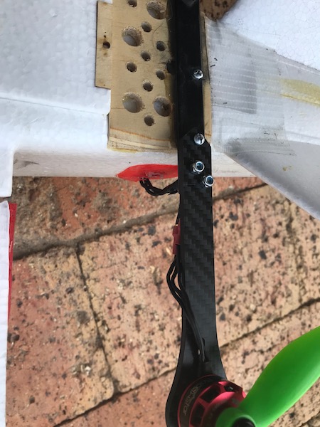
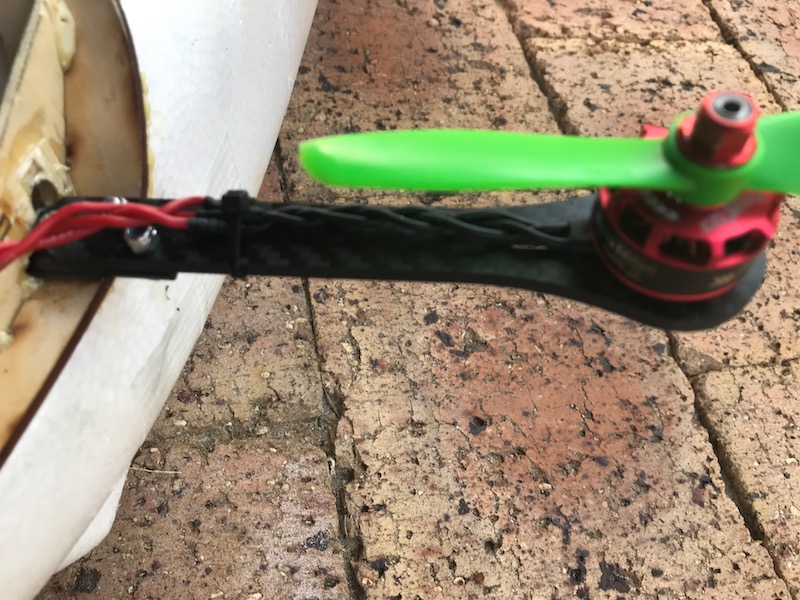
This is our (WestCoastUAV) miniTalon conversion. I finally got around to using the mini quad arms and they worked out heaps better than printed mounts. It flew today in hover then we bungeed it to autotune the fixed wing side which went well.
The Qbrain I am using for the ESC did not work out as it is getting too hot and cutting out. Changing to discrete ESCs if they ever arrive.
Motor is a NTM3536 910kV with an Aeronaut 10x8 folder, battery at the moment is a Multistar 6000mAh 4S, Quad motors are RacerStar 2306 2400kV with 5x4.5 Gemfan bullnose props.


2 Likes
Very colorful! When I saw “WestCoastUAV”, I immediately think California and then the wing colors looked Italian. I see now that you’re closer to Sam. 
2 Likes
In a VTOL plane, what is the ideal thrust to weight ratio for the plane drive system? I’ve read it can be quite a bit less than a traditional plane as the quad is in motion so static thrust is not as significant.
Sorry for the thread creep.
Dave
1 Like
Hi David
It really depends on your airframe. You will still need “extra” thrust to climb, above the thrust required for cruise, but that thrust can be generated at higher airspeed rather than at the lower airspeeds for takeoff where a high pitch prop might stall. Unlike a multicopters or aerobatic planes the thrust to weight is not necessarily the right metric to design a quadplane by (or any plane) for range or endurance, as the thrust should actually overcome whatever drag, including induced drag from lift, the aircraft has at that particular airspeed.
For best range or endurance it is important to have a propulsion motor and propeller setup that produces “just” enough thrust to overcome the drag at that particular desired airspeed. A way to think of the relationship of thrust and drag is that the consequence of drag is that it reduces aircraft altitude, and that “just enough” thrust will keep the drag from making the aircraft descend. Also one can produce more thrust than is required (from say a prop that has a over diameter prop) and one can produce thrust at the wrong airspeed (from the wrong prop pitch). So whilst a prop with good low airspeed thrust is good for takeoff, it’s unlikely to be ideal for the thrust required at high speed cruise. Further on launch a prop needs extra thrust to accelerate the aircraft to above stall speed and for climbout, a quadplane does not as it uses the quad motors for takeoff and can maintain enough lift for flight whilst the forward prop can slowly accelerate it to over stall speed, where the wings can take over the lift required to maintain altitude.
Typically to get the most efficient cruise you first find the aircrafts best glide slope airspeed and fly about 1.32 times faster for best range, and 1.32 times slower for best endurance. This “most efficient cruise” is also known as Carson’s speed. So once you know if you want best endurance or best range, you then select a motor/prop that produces enough thrust at that aircraft airspeed. Note that with electric motors, unlike combustion engines, you can easily over dimension the electric motor to produce enough thrust for climbing, whilst still being able to throttle back for just enough for cruise, without it negatively impacting motor efficiency. That means provided you have enough motor torque and RPM you should be able to configure the prop for “just enough” thrust to overcome drag at cruise, and still have enough reserves to climb at cruise airspeed. The prop will simply be “tuned” to the best cruise airspeed, rather than the typical compromise to allow for low stall speeds.
Given that lift is also dependent on airspeed, adding weight, in the form of batteries, also means that the Carson speed increases and typically also range. Adding weight to any aircraft increases wing loading, and also stall speed. But if you have a “unlimited runway” in the form of the quadmotors, this results in better overall aircraft cruise performance as you no longer have to have wings with a low stall speed to safely takeoff and land, nor a high thrust, low airspeed forward prop that is not effective at cruise.
Hope that helps.
Regards
Sam
1 Like
Sam,
Thanks for the reply. I think I am going to convert an FX 61 into a VTOL. I’ve read good things about the airframe. While I’ve looked, I can’t find any information about the airfoil to determine stall speed or L/D max which is typically max range.
Do you have ball park suggestion for plane t/w. I am thinking .50 is more than adequate. Then I can adjust prop diameter and pitch to maximize efficiency. But i have to get started somewhere!
Thanks,
It has been quiet some time but I have not been resting 
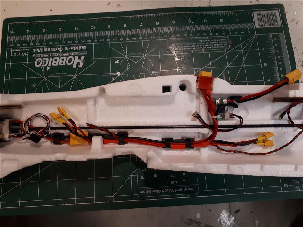
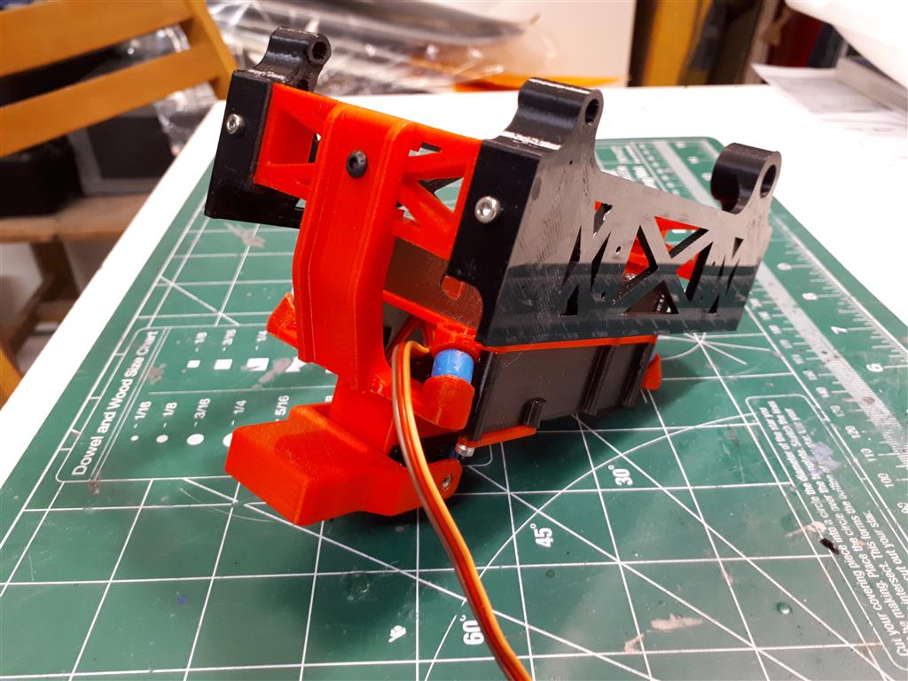
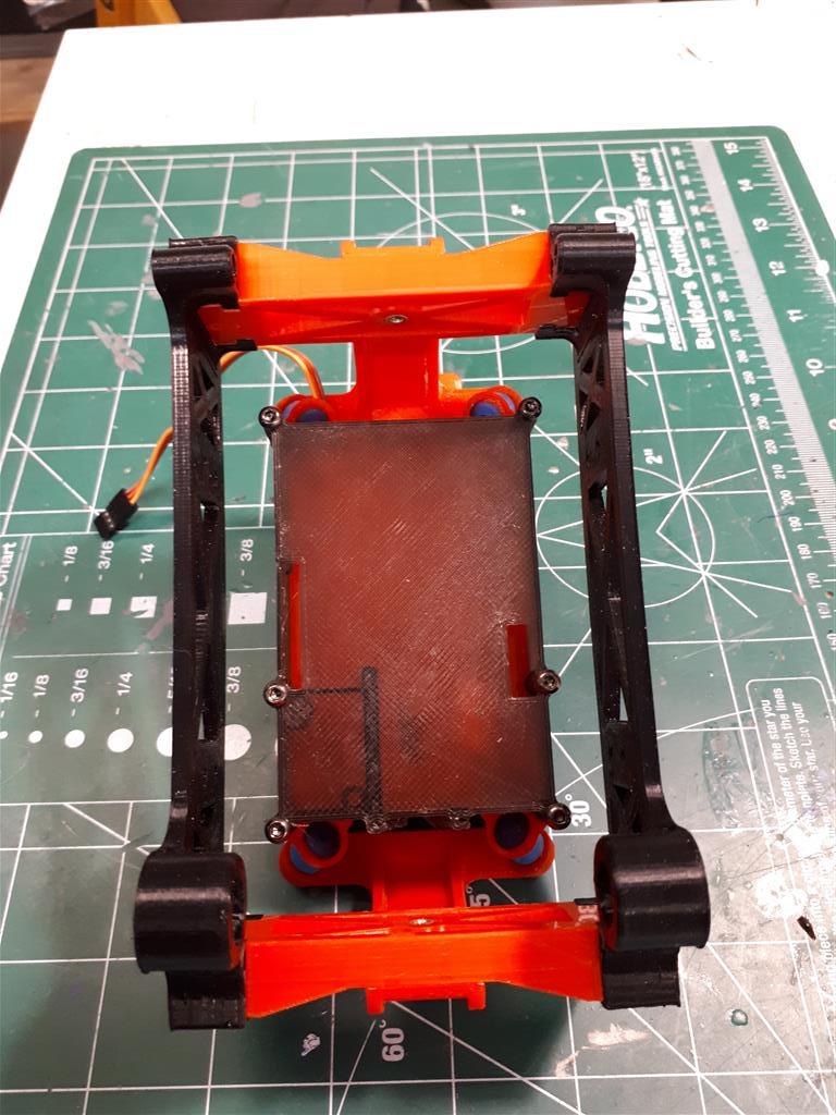
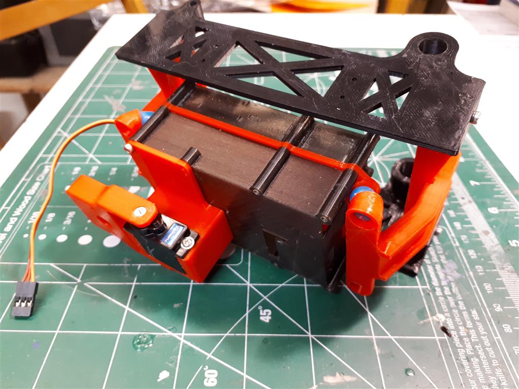
Inspired by the excellent Mozzie, Sam at PerthUAV and Greg, I have made some new parts and slightly modified some of PerthUAV’s to make it possible to have the avionics in the center bay under the wing (as opposed to behind the wing in their design).
The reason for this is that, for this project, I don’t need to carry any additional payload (at the CG). By moving the avionics forward I can reduce the all up weight as I do not ned to balance out the reward avionics.
I will of course make the STL files available when everything is confirmed to fit as it is supposed to 
1 Like
Nice designs and 3d prints ronsard!
I’d like to add a link to them if I may from the Mozzie docs?
The reason why the avionics was further rear is because of the vial holder which needed to be on the CoG, as in the competition the person could not change the CoG after placing it. For non competition aircraft that isnt required. I also like your damping system better than ours!
(EDIT P.S. How do you install and remove the avionics package after the fuselage is assembled with the custom 3D printed wing box? Ours was mounted with two screws through the fuselage so it could be easily and quickly replaced.)
Hi David,
I’m not intentionally trying to be vague, but rather just trying to explain of the dynamics of quadplanes and how they differ from conventional plane configurations. I agree that you need to “start somewhere” and there’s two ways to do this:
- you get the FX61 airborne by whatever propulsion means and determine Carson’s by completing some zero propulsion descent rate tests. One way is to power down from high speed flight and maintain exact altitude until stall, say using alt hold. (which BTW is not always recommended with wings that can go into a unrecoverable flat spin even from 3-4 mistakes high). Ideally the quadplane setup would already be installed for this to aid recovery, and give realistic drag.
- you install a motor with significant power, so more than required for cruise, and go through a series of tests to determine the best endurance/range for each prop.
Note that even a 30g 2206 sized motor can produce over 2kg of thrust now a days, so there is no real benefit in having a undersized, lightweight motor that only does a specific thrust to weight ratio to save a few grams. The thrust to weight ratio also doesn’t take into consideration at what airspeed the thrust is achieved. Hence why all high speed aircraft have variable pitch props. If your aircraft doesn’t have the right amount of thrust at the desired cruise airspeed, you’re essentially stuck in the “wrong gear”. In comparison the Mozzie drivetrain has better than 1:1, but only once the prop is at enough airspeed where it has enough “traction” and doesn’t stall. The efficiency defining factor with electric propulsion is the correct prop, that in hobby products are sometimes only 10% efficient at converting motor torque into thrust. This is where most gains can be achieved.
One place to start is to copy some other models like this one with 100km range:
According to the current draw data there the drivetrain power requirements are similar to the MT/Mozzie and he uses an even steeper pitch prop to achieve it with roughly the same MTOW. So the same motor prop from the Mozzie should be within the ballpark. Also note that even if the prop efficiency was high and around 10g/W that FX 61 is achieving that range with only around 400g of thrust at cruise, so 0.25. It’s likely you’ll need similar for a QP setup plus 10-20% more depending on how streamlined and small the QP setup is.
Hope this helps.
Regards
Sam
2 Likes
Thanks Sam I fully understand your requirements for a CG located payload bay for the Outback challenge.
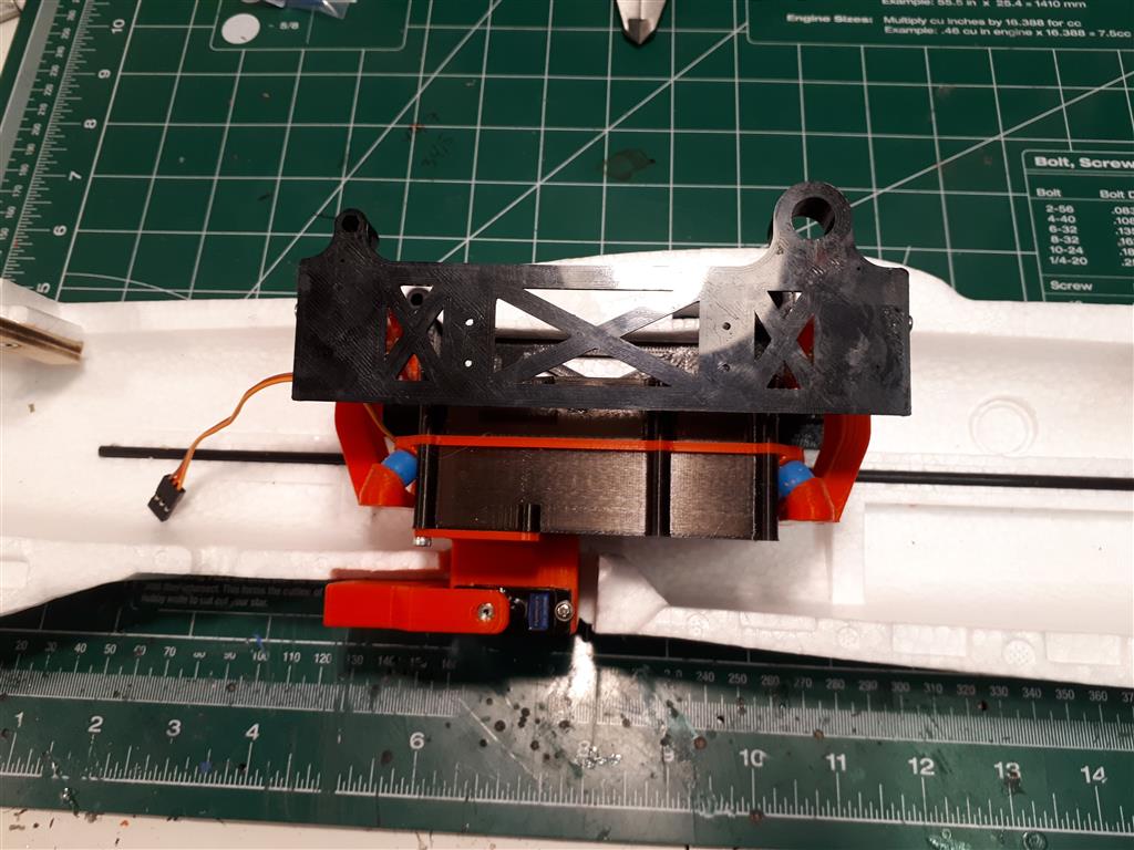
The damping is inspired by the Omniarc one, and I have used it successfully in several large hexacopters.
In my design the complete avionics package can be removed in two different ways (or combinations of both).
The “uprights” for the lower damping balls can quickly be unscrewed with one screw each accessed from the front and rear compartments (black screw seen in the pictures). Then you can pull the complete assembly out through the center bay.
It can also be undone by sliding out the dowtalils for the front and rear frame center spars. These are secured with two screws each (silver ones in the pictures). These screws might also be omitted as the fit is quite tight.
No problem with the STL files. I will make them available when I see that everything fits nice Sam if you are interested, I should be able to share the cad files (fusion 360) as it makes refinement easier.