Seems a good idea to link this here
http://discuss.ardupilot.org/t/mini-laser-module-interface-question/11697/40?u=skyscraper
This is something that I’ve agonized over for ages. In the end we selected the PCA9509 buffer for the I2C to improve the performance. We didn’t want to use hardware with a different physical protocol, such a differential signaling, otherwise there would be compatibility issues with the host systems.
I was thinking to putting this inside a cable, so it is converted to traditional I2C at each end of the cable, so you can use existing board connectors and existing hardware. The only thing to be aware of is to try to cater for up to 1 MHz I2C clock rates, if possible
To isolate the output I am currently planning to use a simple dual 74HC66 SPST analog switch. I cant see much advantage to the dedicated I2C buffers and they all seem to come with warnings about a raised Vout low voltage due to the mechanism used to detect data direction, which may cause issues with the above differential I2c IC.
EDIT Strike that it looks like you arunning at a lower voltage ! (In your case though maybe no buffer is necessary?)
I like the cable idea using the differential I2C standard - it could be really useful.
The PCA9509 buffer in the LW20 is serving several purposes. It has better drive capability for higher capacitance so it should work better on a longer cable. It also provides static discharge protection and improved noise immunity. Additionally, the LW20 can disconnect itself from the I2C bus which could be used to provide isolation in the event of a fault condition. And of course it allows the LW20 to use different internal voltages :).
1 Like
LW20 is Supermen of Lidars it seems…
Maybe Ant-Man 
1 Like
Hello Laser_Developer,
I´m quite excited about your new LW 20.
Can you confirm, that the device is usable plug´n´play with the latest Arducopter AC 3.4?
Did you get feedback from the developers?
Thank you in advance!
Ulrich
@Lubive - thanks for the question Ulrich. We have included a “legacy” command set in the LW20 so that it will be immediately compatible with existing AC and AP versions. However, these don’t have the scanning capability, only the laser altimeter. I hope we’ll be able to offer the full Ardupilot functionality soon but there is still lots of work to do before we reach that point. The good news is that the LW20 does have all the features built in and I’ll post more information as we move forwards.
@Laser_Developer To clarify, plugging the lW20 into the Pixhawk today will only give which altimeter reading? The longest or shortest (surface or ground)?
Hopefully the shortest.
@cndnflyr - The default is to provide the shortest result as Rob says  . This is for safety reasons although in most circumstances when the target surface starts to get closer, the shortest and longest readings are usually the same.
From your web store, it looks like you can choose either IC2 or Serial. Since it’s a sealed enclosure, I’m assuming you can’t switch after the fact?
Are these cables pre-terminated with some connector? How long is the cable?
Thanks! Looks like a great product!
@jprouty: It is possible to change the comms format after purchase the LW20 by opening the unit and moving the wires to a different position on the internal connector. Similarly, damaged wires can be replaced or longer wires can be added if needed. The plug and wire part numbers will be in the manual along with instructions on how to make changes. All waterproofing seals are neoprene rubber so the unit can be open and closed numerous times.
The standard wire length is 35 cm and it is unterminated so that you can add whichever connector you prefer. The wire is shielded and the shield is internally connected to the Aluminum housing to reduce the effects of EMI.
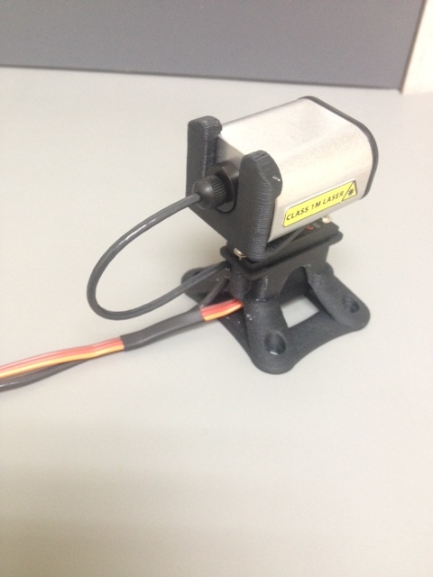
Here’s a picture showing the cable gland at the back of the LW20. In this case the unit is driving a servo directly and it’s mounted on a small test stand. The cable is a special flexible type like the ones used in printers so that it can withstand millions of flexing cycles.
Thanks for the details! Very useful reply.
Wait, “the unit is driving a servo”… Is the unit the LW20?
Yes, the LW20 directly drives the PWM signal used to position a servo.
In the LW20 there is a complete servo control system that lets you define the parameters of the servo that you want to use - things like the maximum and minimum PWM durations and the scale of the servo (number of us per degree of movement).
You can instruct the LW20 to aim the servo in a particular direction or you can select the automatic scanning mode that sweeps the servo backwards and forwards whilst automatically synchronizing the laser measurements. The data from the scan is available either as live streaming (angle, first return and last return) or else you can use the internal alarm features to warn when something gets too close. The alarms require much less processing by the host controller.
I’ll post a lot more info about the LW20’s capabilities over the next few weeks as our new GUI application and detailed manuals go online.
Thanks for the clarification! That’s very cool  !!!
!!!
I have two LW20 lasers and I’m looking for a solution. I want to be able to read the long and short returns remotely so I can confirm the height above ground and height above vegetation of our UAV towed payload. At the same time, I would like it recorded so I can use the data to post process an elevation alongside the GPS z readings. This isn’t implemented in the Arducopter code yet and I’m wondering if anyone else has a solution?
With Arducopter 3.5 you can see them side by side.
But you do not have shart and long info AFAIK.