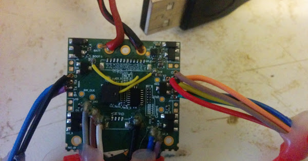
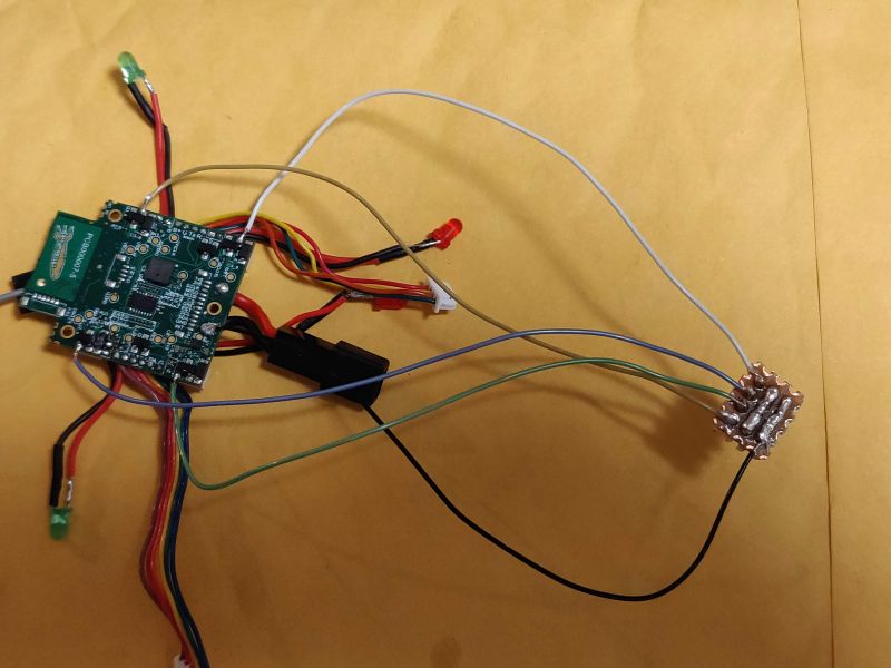
If you want to hack at the flight board on the skyviper, this photo may be useful:
On the left we have the pins going to the Sonix video board. On the bottom left we have 3 pins for a USB cable. On the lower right we have 3 pins for going to the debug console (57600 baud, black wire is ground)
On the right we have 6 wires going to the GPS/mag board.
The yellow wire is for putting the STM32 into DFU mode for flashing a new bootloader over USB. It is cut in this picture.
7 Likes
This is a nice tiny implementation of the FC,companion computer, radiolink, & cam for the pixhawk ecosystem. It appears that the brushed motors are just driven through a mosfet. Are these just normal pixhawk pwm channels (maybe with different pwm rate)?
I’m looking at my options for either driving standard esc’s or servos. Neater to just remove/bridge the mosfet and use the connector than start soldering to TQFP pins.
1 Like
yes, you just set MOT_PWM_TYPE to 3 for brushed motors, and set RC_SPEED to your period (the skyviper uses 16000)
@tridge i assume adding the usb connector is the safest way for loading non standard firmware on to the flight controller.
Is there any reason that you cannot use a standard ArduPlane firmware on this FC rather than Arducopter? (obviously on a different airframe  )
)
What target is it built as? (px4fmu-v?)
1 Like
Awesome! @tridge, thank you for this very nice photo and the helpful comments. I just listened to your talk, “More Crazy Flying Machines,” from LinuxConfAu 2018 where near the end you mentioned soldering on this very board. Can you provide more details about the 3 pins going to the “debug console”? I can indeed see that the black wire is connected to ground, and the other two wires are connected to transmit and receive. Are the voltages on these pins fully RS-232, TTL (5V), or CMOS (3.3V)? I will assume 3.3V and work my way up from there. Is there a schematic that would answer this question? And lastly, is this “debug console” useful for debugging with GDB, JTAG, or something else?
UPDATE: I will find out what can I learn on my own and report my findings back to this thread. Andrew, you really have already provided all the important details between your talk and this post. I’ve never used GDB on an embedded system. This is going to be so much fun!
SUCCESS: The debug console works at 3.3V with a TTL-USB adapter set to 3.3V.
On power up “debug console” dumps the following information:
[init] looking for microSD…
nsh: mount: mount failed: No such device
sercon: Registering CDC/ACM serial driver
sercon: Successfully registered the CDC/ACM serial driver
[init] USB interface connected
booting with no microSD
Running rc.APM
Mounting binfs
binfs mounted OK
nsh: rm: unlink failed: No such file or directory
uorb started OK
Starting ArduPilot
Starting ArduCopter uartA=/dev/ttyACM0 uartC=/dev/ttyS1 uartD=/dev/ttyS2 uartE=/dev/ttyS6
initialised /dev/ttyS3 OK 1024 5ArduPilot started OK
12
rc.APM finished
initialised /dev/ttyS1 OK 1024 5
12
NuttShell (NSH)
initialised /dev/ttyS2 OK 1024 5nsh> 12
initialised /dev/ttyS6 OK 1024 512
Storage: Using flash pages 22 and 23
Loaded defaults from /etc/defaults.parm
Starting driver adc start
adc init done
ADC started OK
Starting driver fmu mode_pwm4
fmu mode_pwm4 started OK
SPI device cypress on 2:1 at speed 2000000 mode 0
AP_I2C_0 on I2C bus 1 at 0x55 (bus: 100 KHz, max: 100 KHz)
I2C device bus 1 address 0x55 closed
AP_I2C_1 on I2C bus 2 at 0x55 (bus: 100 KHz, max: 100 KHz)
SPI device mpu6000 on 1:4 at speed 500000 mode 3
AP_I2C_2 on I2C bus 1 at 0x63 (bus: 100 KHz, max: 100 KHz)
Loaded defaults from /etc/defaults.parm
AP_I2C_3 on I2C bus 2 at 0x10 (bus: 100 KHz, max: 100 KHz)
SPI device mpu6000 on 1:4 at speed 500000 mode 3
The debug console returns an “nsh>” prompt in reply to a carriage return:
nsh>
nsh> ?
help usage: help [-v] []
[ dd hexdump mkfifo pwd umount
? df kill mkrd rm unset
cat echo losetup mh rmdir usleep
cd exec ls mount set xd
cp exit mb mv sh
cmp free mkdir mw sleep
date help mkfatfs ps test
Builtin Apps:
adc
tone_alarm
fmu
bl_update
mixer
perf
reboot
top
nshterm
mtd
ver
usb_connected
otp
uorb
pwm_input
px4io
oreoled
sercon
ArduPilot
nsh>
At this point I doubt my Linux host is actually talking to the target.
Eager to try out cross-debugging with gdb for the first time:
arm-none-eabi-gdb ./build/px4-v3/bin/arducopter
I got this error:
arm-none-eabi-gdb: error while loading shared libraries: libncurses.so.5:
I found it helpful to do the following update and install:
sudo apt-get update
sudo apt-get install lib32ncurses5
It seems a good sign that gdb reads the file with no errors:
arm-none-eabi-gdb ./build/px4-v3/bin/arducopter
GNU gdb (GNU Tools for ARM Embedded Processors) 7.8.0.20150604-cvs
Copyright © 2014 Free Software Foundation, Inc.
License GPLv3+: GNU GPL version 3 or later http://gnu.org/licenses/gpl.html
This is free software: you are free to change and redistribute it.
There is NO WARRANTY, to the extent permitted by law. Type "show copying"
and “show warranty” for details.
This GDB was configured as “–host=i686-linux-gnu --target=arm-none-eabi”.
Type “show configuration” for configuration details.
For bug reporting instructions, please see:
http://www.gnu.org/software/gdb/bugs/.
Find the GDB manual and other documentation resources online at:
http://www.gnu.org/software/gdb/documentation/.
For help, type “help”.
Type “apropos word” to search for commands related to “word”…
Reading symbols from ./build/px4-v3/bin/arducopter…done.
(gdb)
But somehow I doubt my Linux host is actually talking to the target. I am hacking in the dark. I need to learn how to get remote debugging working on the target. So I read:
On the host,
GDB already understands how to use this protocol; when everything else is set up, you can simply use the `target remote’ command (see section Specifying a Debugging Target).
On the target,
you must link with your program a few special-purpose subroutines that implement the GDB remote serial protocol. The file containing these subroutines is called a debugging stub. On certain remote targets, you can use an auxiliary program gdbserver instead of linking a stub into your program. See section Using the gdbserver program, for details.
And I read more:
Debugging ELF Loadable Modules in NuttX
http://nuttx.org/doku.php?id=wiki:nshhowtos:elf-debug
@nick2204, I use the master branch from SkyRocketToys/ardupilot and I configure board=px4-v3 so I think you want px4fmu-v3. But I’m beginning to wonder about my build because it still uses NuttX which I thought was replaced by ChiBiOS.
Hi @Vincent_Randal, to build for SkyVIper, you will configure board type skyviper-v2450?
./waf configure --board skyviper-v2450
./waf copter
I am following this doc and building plane for SV.
I prepared my environment using virtual machine with Vagrant. It creates build environment with few lines of entry.
http://ardupilot.org/dev/docs/setting-up-sitl-using-vagrant.html
(If on recent Win 10, vagrant ssh does not work due to private key error. I need to use other terminal to connect to port 2222 with key in the tree.)
Once SITL VM environment is ready, run this script to set up gcc-arm-none-eabi etc.
Tools/scripts/install-prereqs-ubuntu.sh -y
Exit and login to make env variable effective, it is ready to build following the first doc.
Hope it helps.
Thank you @Satoru_Sasaki
waf-light: error: option --board: invalid choice: ‘skyviper-v2450’
choose from
’aero’, ‘aerofc-v1’, ‘bbbmini’, ‘bebop’, ‘bhat’, ‘blue’, ‘dark’, ‘disco’, ‘erleboard’, ‘erlebrain2’, ‘linux’, ‘minlure’, ‘navio’, ‘navio2’, ‘px4-v1’, ‘px4-v2’, ‘px4-v3’, ‘px4-v4’, ‘pxf’, ‘pxfmini’, ‘raspilot’, ‘sitl’, ‘urus’, ‘zynq’
Previously, I posted these build steps that work for me and my Sky Viper v2450GPS hardware:
https://discuss.ardupilot.org/t/linux-build-for-skyviper-arducopter-fails-with-build-errors/31549/2
My concern is that Ardupilot still builds with NuttX instead of ChiBios. I am surprised to still see NuttX in the build.
I see, sorry I forgot you are building on SkyRocket repository. I think it is before ChibiOS and not updated since it is merged to master.
To get ChibiOS build, you need to work on master. You cannot set parameter through Sonix board web interface, but I can still use other functionality in my case, both copter and plane.
UPDATE: I’m optimistic to be single stepping through ArduPilot code on Sky Viper hardware very soon using the Black Magic Probe so graciously mentioned in the nice documentation here http://ardupilot.org/dev/docs/debugging-with-gdb-on-pixhawk.html
Again, I’m new to ArduPilot. I’m not new to firmware development, but a lot has changed. I have a lot to (re)learn. The gdb debugger has come along way since I used it over 20 years ago. Namely, affordable devices like the Black Magic Probe provide a gdb server for use with embedded systems with JTAG or SWD. Just awesome!
It’s conceivable the Sky Viper v2450GPS Flight controller board supports SWD (Serial Wire Debug) on it’s “debug console” mentioned at the beginning of this thread. Does it? Does anyone know if it does? I will purchase a Black Magic Probe and give it a go and report my findings here. It’s a privilege to help out if I possibly can.
UPDATE: Problem solved. The back of the flight controller board has two connector pads clearly labeled SWDIO and SWCLK. You can see them in tridge’s photo at the top of this thread. Before a few hours ago that meant nothing to me.
(In case my update to my previous message does not trigger an email to the contributors to this thread. Does it?)
How might it work if upgrade my Sky Viper motors to brushless motors and add an ESC (electronic speed control) suitable for the new bigger motors using a separate battery? I might just try it if there are settings for MOT_PWM_TYPE and RC_SPEED that would enable the Sky Viper v2450GPS flight board to provide a suitable control signal.
Hi @Vincent_Randal, MOT_PWM_TYPE should be 0 (if use common RC ESC), RC_SPEED should be 490, could be higher.
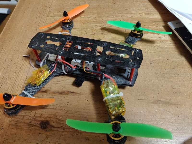
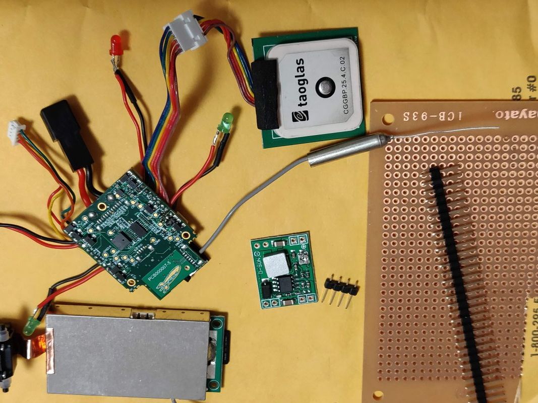
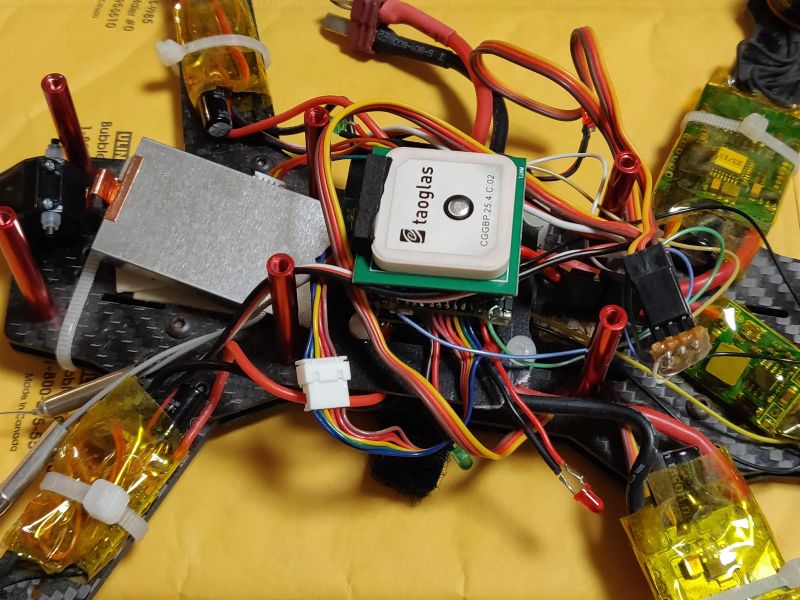
I have loaded Sky Viper controller on brushless quad. It is straight forward, I document quick memo here.
Used old 250 quad I have not flown for 3 years or so. Unbrekable but heavy like a brick. Uses 3S 1400mAh, flight time is 10 min or so. ESC firmware is Simonk. 5 inch prop.
This quad motor is for 3s battery, prepared cheap regulator. Gave up voltage monitoring.
I have not updated firmware to master. As is out of the box. Will use default toy TX. Can use Web interface parameter menu.
Solder wires to 4 FETS and ground.
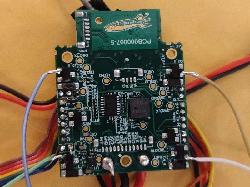
Wire to pin terminal for 4 ESCs.
Fix flight board somehow, done. Weighs 310g without battery…
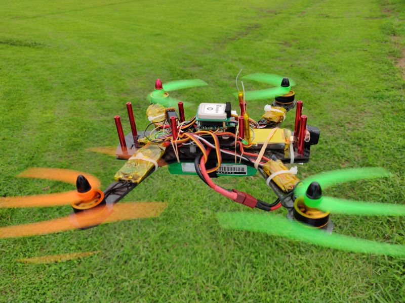
Calibrated 4 ESCs with servo tester, changed MOT_PWM_TYPE to 0, (have not changed RC_SPEED…) Verified it can arm and motor spins correctly on bench using Web interface and Mission Planner.
I needed to lower PID values as minimum as possible in Mission Planner. Once it can fly, I ran autotune. Attaching log file which was able to do short auto mission.
5 Likes
Hey, awesome hack! I just bought an extra used SV with the same idea in mind (also have an old f250 with brushless I haven’t used in a long time). But it looks like you beat me to it! Haha
Anyways thank you for sharing your experience! I will be trying as soon as my spare gets here. Ill also be adding an onboard RPi zero w running dronekit and possibly an LTE dongle to interface via a web API.
If i can make this work ill be looking into a lighter frame but not sure which frame to use since it has to be light but also have enough space for A LOT of components.
Any ideas?
Lighter frame I do not know. I can find similar sized 240mm frame 60g or so. For lightest or longest duration, I am thinking old AR Drone frame (geared brushless) which can fly at 400g+.
You mean Raspberry Pi APSync? I am not familiar with that but agree SV 2450GPS is too valuable to throw away with high quality parts. It is a waste 10s of thousand SV 2450GPS will be thrown away after motor worn out. 
Very good work. You mentioned firmware for the ESC which has me wondering about ESC function implemented in ArduPilot/ArduCopter code and if it can create the correct PWM control signals but not with enough current due to the limits of the Sky Viper v2450GPS hardware.
I mean a raspberry pi zero w (comes with a wifi board) or a regular zero running dronekit.
I have not looked into APsync, I’m familiar with python and dronekit seems sufficient.
Thanks @Vincent_Randal. SimonK ESC is a basic firmware which can respond to faster PWM up to 490Hz compared to ESC for plane, similar to BLHeli, I am getting PWM signal only from SV board.
ESC is connected directly to 3s battery, SV board is powered through regulator (which I set to 3.2V or so).
Very nice @Satoru_Sasaki. I think I want to duplicate your configuration. I very much the idea of getting PWM signal from SV board. Very nice work you have done @Satoru_Sasaki