I have pushed changes to support the fast timer pin capture work that David Sidrane did in PX4Firmware.
To use it you need to set CAM_FEEDBACK_PIN to 53 and attach the feedback pin to AUX4. Apart from that it works the same as the previous code.
It is PX4 specific unfortunately, but should give feedback triggering with microsecond width pulses.
Cheers, Tridge
@tridge could you share how this works? It seems AP_Camera::capture_callback() just sets a flag instead of doing anything and the message is only actually sent by the main thread in the vehicle code.
In Linux we could implement something similar by using interrupts.
Hi Lucas,
The basic functionality is already supported with Linux. The limitation is that it can only trigger camera feedback if you have a pulse width of over 1ms (2ms to be safe). The change allows a very narrow pulse (such as 1us or so) to be used on px4. Typically this functionality is used with camera flash hotshoe pads, connecting them to the GPIO pin, possibly with a level shifter. Some hotshoes put out quite short pulses, so this change makes that reliable.
The way it works is to setup a timer capture pin in NuttX, using a dedicated timer channel. I don’t know how feasible that would be on Linux. If it is feasible we could add a HAL interface for it and implement the interface via a functor callback for each HAL.
Cheers, Tridge
How does this differ from the camera feedback solution that was recently introduced in Ardupilot?
@iskess,
It allows for much shorter pulses from a camera hotshoe while still triggering correctly. For some cameras this means you don’t need to add an external circuit to ensure the pulse is 2ms wide.
Setup is the same as previously, but you must use AUX4 as the feedback pin.
Cheers, Tridge
Well… We could just trigger the interrupt on rise edge. If it’s not required to capture the time when the interrupt happens, just setting the flag is pretty easy to do.
yes, if the hw supports edge triggered interrupts on pins then we can indeed use that. There is a parameter (CAM_FEEDBACK_POL) that selects if it is a rising or falling edge, so we’d want to support both if possible.
Indeed. I’ll work on supporting it soon.
Hi, I am asking here because there is no documentation on how this feature works.
I have PLANE 3.7.1 - two pixhawk 2.4.6 clone and another original doing same thing
My circuits use 5V from the rail and thanks to a photodiode reading my Canon LED, feeds from 0V to 5V to the CAM_FEEDBACK_PIN, it doesn’t works so I removed the circuit and measured what happens to the CAM_FEEDBACK_PIN and:
when the pin is set as CAM_FEEDBACK_PIN and at least one picture is taken, the pin begins to feed 3.3V and stays on until lipo remove, so reconnect lipo, arm, do the shutter commands and again 3.3V back, I don’t know if it’s a bug or my fault, I made a video here CAM_FEEDBACK_PIN output 3.3V when it should not
Thank you
I don’t know if a bug exists or not, but please don’t say there’s no documentation: http://ardupilot.org/plane/docs/common-camera-shutter-with-servo.html#enhanced-camera-trigger-logging
1 Like
Sorry Francisco, I had to say there is no documentation on how it works eletrically so anyone can make an adapter, I searched a lot and I found some information only on the Tuffwing site and here https://github.com/ArduPilot/ardupilot/issues/2289
Thank you for the great work
I would say that’s a bit out of scope - it would still be accepted in our wiki and is valuable information, but not something we should make mandatory to have.
In any case the feature seems to be working for others, if your issue is making an adapter I think you should use the thread you opened before to ask how others did theirs.
The circuit I made works well on the input pin of the Emlid Reach RTK and there is no voltage on its pin, i will continue to search and if I find a solution I will produce documentation for everyone.
Thank you
I was wrong, the Reach has voltage too, I have resolved the problem and updated the thread CAM_FEEDBACK_PIN output 3.3V when it should not
the only strange thing is the TRIG events are doubled but I am testing at home, I will test on the field.
thank you
Are they really duplicated or do you just have an extra TRIG message in the beginning? If it’s the latest, that’s a known bug.
1 Like
I will test on the field and let you know, thank you
Dear OXINARF I finally tested on the field and I got equal entries of TRIG and CAM, tested the LOG with Notepad++.
Then used the Geo Ref tool in MP and the magic happened:
Photo IMG_0xxx processed from CAM Msg with 0 ms shutter lag.
On all the pictures
That’s great. The shutter lag is configurable by you, Mission Planner doesn’t know that.
Keep in mind that the current accuracy of the messages is still not that good. Hopefully the following PR will solve the 50Hz resolution of the CAM messages on the logs.
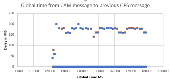
The hotshoe can be recorded even if the signal is far under 1 ms, but the timestamp written to the log is only recorded at 50 hz (The CAM loop rate). The following data from the CAM messages (from @Tuffwing_UAV hotshoe recorder) was recorded on plane 3.8.4 about 6 months ago. The mode was about 180ms from the previous GPS tag, and if it wasn’t 180ms, it was 160 or 200. There was a 140ms and a few smaller ones at the beginning of 40, 60, and 80ms. That consistency of stepping 20ms is obviously systematic at 50Hz and not real.
Most users are probably good with 20ms, but not me when I want to interpolate going 15-20 m/s. The documentation has been somewhat misleading and confused with the “Fast capture” discussed here. They are NOT the same. Just because Ardupilot can detect a microsecond pulse doesn’t mean that it applied the correct timestamp has been applied to that pulse.
Link to log is in the github post above.
1 Like