Hall sensors as mauch have, they are the way to mesure current today, but the fact is I can live without it, and I have do it for a long time on small quads and planes with a good lipo control.
It’s an other component for a failure, where all the energy ever been used has to pass through it.
Are they reliable for long term?
It’s only a thought like simple things have less failures, a day of dumbs thoughts maybe, let’s see what I will think tomorrow.
I tend to agree with this. I fly four different electric helicopters with various battery configurations depending on payload and flight speed. So the current measurement is pretty much totally useless as one day I may be flying a 6600 12S configuration, and the next a 10,000 mAh 12S configuration, and I don’t go into the params and reset the whole system up to measure the different battery configuration. I just disabled all that and use the voltage.
My ESC does a “soft” shutdown at 3.0vpc, or 36.0 volts under load. If I’m getting down to 40 volts I know it’s time to look for a place to land because I only have a couple minutes left. And as the batteries age their mAh capacity drops. So unless you set up the measurement system to compensate for it, it’s off anyway. Voltage is a good indicator every time because no matter how many mAh were consumed during the flight, it’s still going going to go into “soft” shutdown at 36.0 volts and have to autorotate the heli if I don’t do something about it.
I do have Castle Link Live telemetry to my RC radio and I show watts on the radio screen so I know how much power the heli’s engine is producing. But that’s just a “nice thing to know” and voltage is still the ultimate determinator as to when it’s necessary to land.
1 Like
For me both voltage and used mAh is usefull and does not replace each other.
Voltage is a good way to know that NOW is the exact time to land. On 3S battery if I reached 10 volts then it means I need to land right now.
But on the mid-flight when my voltage, lets say 11.2V - it is almost useless to meassure the available remaining flight time.
At same time the mAh used is the way to know the APPROXIMATE (error is less than 10%) remaining battery percentage at ANY time. Even simple shunt sensors works well for me.
Of cource it is just my expirience and maybe mAh is not so accurate if you fly 3D aerobatics or helis etc.
Beside the time estimation there is another point in current sensor. It shows the wind conditions. One day I flied high and I saw a current spikes up to 40A (when my normal current is about 10-15A). This is because copter fighting a strong gusts of wing that I’m was not aware of beeing on the ground.
The value of Hall sensors is that they are reliable. None of the current actually goes through the sensor. The sensor is not part of the circuit.
It kind of does indicate remaining flight time. Because you will typically have some experience flying the particular battery configuration that you are using. So you know how long it will fly, and what the voltage drop is under load by observing it. I run two different timers on my RC radio during a flight - one is counting the engine run time from governor on. The other starts counting once I engage Auto flight mode in flight. Those are also “tools” that I use.
I use sort of the same thing for my piston helicopters. But the voltage monitor on the RC radio is just the generator output to the flight systems power. And I have percent engine torque telemetry from my RevLok governor that is based on throttle opening. Since fuel burns by the clock with combustion engines, I have a countDOWN timer on the radio that starts once I engage Auto flight mode. it’s a much greater challenge with piston engines because the flight times are up to 2 hours and if the estimate is off by 10% that’s 12 minutes of flight time. But by testing ahead of time to determine fuel burn, it’s usually within 2%.
So I would say each pilot has to use what works for him/her. If the current measurment using the power modules doesn’t seem to work and voltage is a better estimator, then use that. The system is configurable to use what you want, or to disable what you don’t want to use. And you can modify the system to do what you want - even if you don’t understand the code you can team up with somebody that knows C++ programming and build your own custom firmware - it is the beauty of flying an open source autopilot system.
It does for sure, but the error is very big comparing to mahs used number.
With simple mAh counter I could fly far away and get back with 10% fuel remaining.
It is impossible for me to estimate so accurate with only voltage.
It can with lower powered aircraft on 4S or lower power. It is WAY off with 12S systems, even using the AttoPilot twin-shunt boards. The reason is the calibration of the shunt or hall-effect sensor. On 3s your operating voltage range is 9.0 - 12.6 volts, for a range of 3.6 volts. On 12S the range is 36.0 - 50.4 volts, for a range of 14.4 volts. So it becomes much easier to use voltage on higher voltage power systems because you have much better resolution, and the current draw is 1/4 of what it is on 3S at the same watts.
Electronics are a magic mistery, it seems to me part of it.
https://www.digikey.es/product-detail/es/allegro-microsystems-llc/ACS758ECB-200U-PFF-T/620-1356-ND/2415201
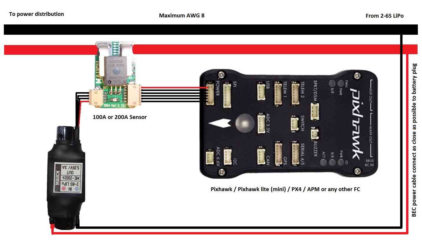
http://ardupilot.org/copter/docs/common-mauch-power-modules.html
http://ardupilot.org/copter/_images/MauchPowerModuleWiring.jpg
LMAO. Mike is right and the pic actually proves it. The wire is routed thru’ that black plastic part to ensure that it is at a known fixed distance to the sensing element. Like in “it goes nearby, but not through”. It’s there to make sure that poets and painters don’t just leave the wire " hanging in the viccinity of the sensor" . If you take a look at FrSky FCS-150 for instance, it has a ring thru’ where your positive wire goes. They may touch, but not electrically.
And current is the MOST important parameter for a multicopter. Once you know your bird, you can start approximating wind-speed at the altitude, and even guess the direction, if you fly grids. It gives you consumption, and if you have your packs labeled (I do) you always know where you are - and the charger will reinforce the picture at the end of the day.
I don’t do racers, and I don’t think AC is the platform to run them on. I mainly do mapping and precision agriculture. Got twenty-something packs, some as old as 5 years, probably approaching 500 cycles each, and I do micro-management on them for a job based on the current consumption from each flight.
I think that’s where the border between recreational/amateur and professional pilots stands. I count myself as a proffesional. Your GoPro may take a beating from a crash, but my FLIR kicking the bucket will put a serious dent to the income, so it’d rather not.
So, current-sensing is life. Your question IS DUMB !!!
Hey Edge, Total current is easy to measure with a Hall effect sensor where the wire goes throught a ferrite ring with the sensor within the gap. A company called Amploc makes them. amploc.com
I use the 100 amp sensor. The calibration is not optimal because it has a large dc offset because it reads +/- current within a 0 - 5 V range. I was able to calibrate it using the existing offset and scale parameters. I modified a 3DR power module by cutting a tab on the pcb and soldering +5V, gnd, signal to a servo connector that goes to the sensor. I calibrated it by tieing down the copter and running it, comparing the sensed amps with the amps measured form my external battery shunt. It’s a bit of effort, but the results can be trusted. I have an 80 amp calibrated shunt that I connected in line with one lead of an extended battery connector. Tie the copter down and hover it with a cord between the battery and the copter. The output of the shunt is connected to a mA meter with a Mobius cam recording the meter reading. What I recharge back into a battery is within a few percent of what the data logs show was used. I just flew my 650 quad with gimbal, fpv ect for 36 minutes with a 16000 mA battery. A best for me. was at 14.2 V just before landing and MP said ~ 20 % left.
Ok, If you don’t want to use current sensing then that is up to you but maybe I can clarify what you are missing out on. (I will repeat some things)
mAh: If you know you batteries then you can get a very good indication of the remaining energy available. When running auto missions this provides the autopilot to pick up human mistakes and land the aircraft safely especially when operating over areas you do not want to land. If you use different batteries it is a matter of changing a single parameter and the user is completly free to do this or ignore it.
reliability: I have never had a current sensor fail when using it below it’s rated current. The hall effect sensors are particularly good as the hall sensor is placed nearby a short in a known geometry to ensure accuracy. So high currents are extremely unlikely to damage the hall effect sensor.
Voltage: Using voltage is a good way of detecting when the battery is about to die and land your aircraft for you (or even shut down your autopilot). However, on higher current / short duration aircraft the battery sag will make it impossible to use this as the voltage varies too much without going to a fixed flight state to evaluate the voltage. In this case the current sensor is used to measure the internal resistance of the battery and predict the resting current of the battery. This makes it more reliable to detect when the battery voltage is about to plummet and you have to land even in high current applications.
Battery impedance: As I just stated measurement of voltage and current lets us predict the battery impedance. This lets us calculate the resting voltage of the battery. The resting voltage does not vary as much as the measured voltage. The battery impedance is also a good thing to watch to find bad batteries.
Gain scaling: The predicted resting voltage is used to scale the PID of multirotors so that you get the same level of stability on both fully charged or flat batteries. Before we did this after autotune a user could get oscillation after charging the battery because the last axis was tuned on a low voltage.
Finally a warning on accuracy. I have found that the mouch sensors have not done their filtering properly and can read poorly especially when driving a single motor. The hall effect sensors uses have a very broad bandwidth and without the correct filtering the high current spikes can be missed causing a lower than expected current measurement.
So to respond to your question/statement: Yes a current sensor has been clearly shown to improve safety and performance of multirotors. While aircraft can be flown safely and effectively without a current sensor I personally consider it a “must have” sensor on all my aircraft. However, each individual user is free to exclude the current sensor or it’s contribution if they wish.
Greats infos, I love dumb questions.
I don’t know electronics, it’s like some magic but this kind of sensor seems reliable
http://www.allegromicro.com/en/Products/Current-Sensor-ICs/Fifty-To-Two-Hundred-Amp-Integrated-Conductor-Sensor-ICs/ACS758/ACS758-Frequently-Asked-Questions.aspx#
http://www.allegromicro.com/~/media/Images/Applications/ProductLandingPageImages/50-to-200-A-Current-Sensor-ICs.jpg
That is precisely the sensor used when 99% of us talk about a Hall effect current sensor. You can see in the diagram that the sensor is not connected to the wire but instead sits next to it.
If you want an all-in-one power distribution board with two 5V ultra stable outputs, one 12V output, Pixhawk ready plug & play connector , Hall effect current measurement up to 200A , with dual battery inputs, take a look at the board I designed : http://www.airbotservices.com/airbotpower.html
Contact me by email (bottom of the referenced Airbotpower web page) if interested to get a quote.
The current measurement is also used to compensate for magnetic interference caused by current flowing through wires.
Yes, compass mot. I forgot that one.
Leonardthall, GREAT summary of the use of mAh, THX
one may wonder why there even could be a long debate about this in another thread
anyway, as regards precise mAh counting, you guys may have a look at the UC4H power brick, it measures current at a rate of 1kHz (could be increased if deemed relevant), so, this one does NOT miss to count current spikes 
(to the best of my knowledge, this is the only available (DIY) device which can do that)
I’d like to mention that filtering can improve mAh counting accuracy somewhat, but is not a substitute for fast current measurements, like the UC4H power brick does!
(this is simply because a filter is linear, while spikes and so on are not distributed symmetrically around the average)
In my experiments I got accuracies of 1-2 % without any calibration.
https://discuss.ardupilot.org/t/uavcan-for-hobbiests/16464/52
https://discuss.ardupilot.org/t/uavcan-for-hobbiests/16464/59
That looks like a good sensor. However, the statement I quoted here is incorrect. It is actually much more correct to say “High sample rate is no substitute for appropriate filtering”.
If you low pass filter correctly you will get just as accurate current average as you would with a lower filter and higher sample rate. It is just easier to implement the filter if you can use a higher cut off frequency.
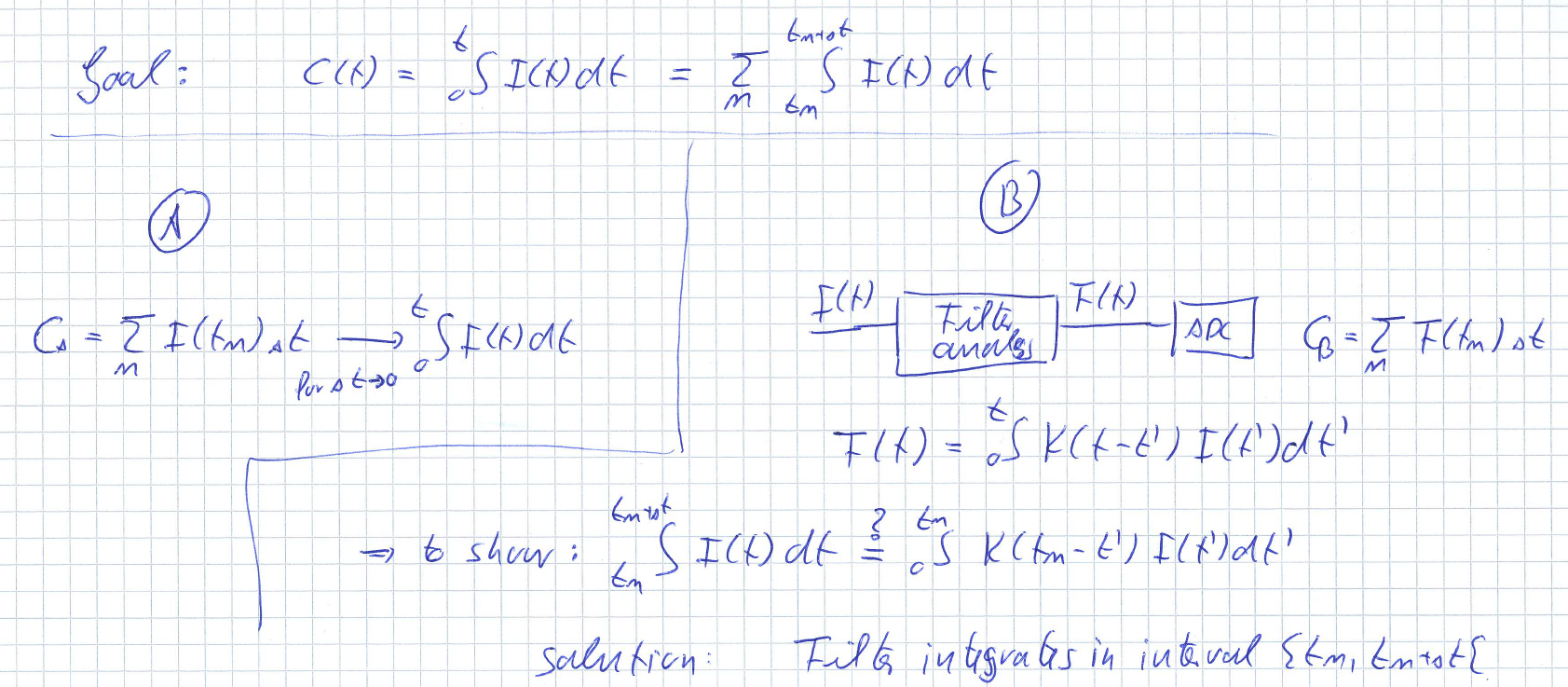
By definition the area under the input and output of a linear time-invariant causal filter is the same assuming unity gain. So when you are integrating the filter response to measure mAh a low frequency filter and a low sample rate will be equally accurate as a high frequency filter with a high sample rate.
1 Like
I disagree with that
a causal filter is not an integrator (except in specific cases)
and “summing digital samples” is not the same as mathematical integration (in continuous time, which is what we need for for accurate mAh counting)

I should add: the reasoning depends on the type of ADC, I’m of course talking about ADCs like that in the STM32
to put the discussion on more solid feet, here a sketch of the two methods under discussion
since you’re saying that it is possible you should be able to give me an explicit filter which is a solution to the “to show” condition, which is not an integrator.
EDIT: sorry, the integral boundaries for the current integrals should obviously be t_n and t_n - \Delta t, not t_n + \Delta t and t_n.