Dealing with Vibrations and harmonics... a competition

I have a competition for you all…

Prize… one full Edison compatible suite with Standard GPS.

Task… A few people have asked what the natural frequency of the cube is. I could just tell you, but where is the community in that?

So… here goes… each of these questions need to be answered in full. Prize will go to the Best answer…

A. Please define each of the harmonics that can affect the Pixhawk 2
B. What is the effect of these on flight
C. How can someone measure this on their airframe
D. If your airframe has vibration in these bands, what can be done to protect the system from this.

We are looking for Human readable answers…
I will be asking the great GNC Dr to verify the answers…

Phil

1 Like

Phil

I will be very interested in some of the answers to these questions, as you know i have this problem. Although i don’ have the experience to answer the questions what i can say in from experience in flight you can hear pulsing of the motors which gets worse with speed until eventually in my case the vehicle will drop if nose very abruptly and then recover.

Best we keep this thread on topic, but have you posted logs? And have you run auto tune?

A. Every harmonic could affect the pixhawk2, depends of the amplitude of each. Since 1st.harmonic (natural frequency), 2nd, 3 st …. n st

B. The copter start to oscillate at pixhawk2´s natural frequency, and the system will collapse.

C. It is not possible to measure with certainty with the pixhawk2 imu´s, because always oscillate at his natural frequency. We can adapt a cellphone to the airframe with app that shown the transform fourier, in order to see the amplitude of natural frequency and harmonics.

D.Change dampening system with others with different k, In order to change the natural frequency W=√(k/m).

To mesure: the natural frequency you need to make a bump test. https://www.youtube.com/watch?v=W3qNb19lplI

This is the log of a very short flight done yesterday. I didn’t an auto tune because i was to scared that something might go wrong given the vibration problem.

2016-12-20 08-51-47.bin (3.3 MB)

I actually think people are missing the vibrations / DSP components Proficnc had in mind when asking the questions.

A. Please define each of the harmonics that can affect the Pixhawk 2
I dont know the exact harmonics that can affect the Pixhawk 2 as I dont know the sampling rates. However, if everyone remembers their classes, the harmonics that will affect the Pixhawk 2 are related via the Nyquist Sampling Theorem. The nyquist sampling theorem establishes the relationship between the analog real world and the digital sampling world. Establishing the sufficient condition of sampling rate permitting a discrete sequence of samples to correctly reconstruct the continuous-time signal with finite bandwidth. This theorem states that we must sample atleast 2x the expected frequency of the system. Thus, since we know our approximated dynamics of the vehiucle occupy x frequency we need to sample at atleast 2 times this value to be able to reconstruct it. An example would be if we sample the IMUs at 500Hz we require that any of the dynamics that we want to measure exist at <250Hz and we would most likely form some variation of high pass filtering on the rest. The issue becomes when the high frequency content becomes aliased into the measured sampling spectrum. An example would be systems that are exhibiting vibrations at 300Hz would alias the signal at 200Hz assuming the above scenario. Therefore, the concerned frequency regions of vibrations are those that are aliased from the higher frequency content into the bandpassed region of where our expected dynamics measurements are. Which leads into the next question.

B. What is the effect of these on flight
The effects on flight can be dependent upon the aliased frequency, harmonics, and magnitude of the result. These can lead to first mechanical airframe instabilities (when if resonating properly can cause catastrophic failure). But, most commonly since most of us arent that lucky (even though I have seen it in human and large helis (>300 pounds) where the system hit ground resonance…the most common problems are poor flight performance because of the inability for the EKF (or whatever data fusion algorithm is aboard autopilot) to correctly decipher the true dynamics data from relative noise and this instability. This will lead to often violent corrections in attitude, and/or very poor tracking performance. Depending upon whether the signal is apart of the inner/outer control loops.

C. How can someone measure this on their airframe
There are actually many ways to measure vibrations on an airfame depending on what you are trying to do with the data. However, I think if I am on the right track in answering the question, the best to determine if the noise is apart of your airfame may be to actually perform undersampling or nonuniform sampling of the data. Both techniques explicitly exploit aliasing as related to Nyquist sampling theorem. For example, when a signal is sampled at a rate less than 2x max freq, the aliased signal will appear at Frequency_Sampling-Frequency_InputSignal, For example let us say our frequency of interest is 100Hz and we sample it at 150Hz. We know the aliased frequency of interest will appear at 50Hz +/- signalbandwidath/2. By varying the undersampling and varying the rate of sampling you can derive out the primary signal frequencies (which I am sure are well documented in the code branches based on their filter routines) you can actually isolate the high frequency vibration content of the airframes.

D. If your airframe has vibration in these bands, what can be done to protect the system from this.
Vibrations that produced aliased signals into these bands need to be addressed for correct performance of the autopilot system. Assuming the question is asking for a mechanical method and not a DSP method here…many of the above are correct. Knowing the frequencies that are aliasing from the higher vibrational content as the above are important as you know that the item producing it will be at a harmonic of it. Once you know this, you can either build out the IMU to isolate it from that frequency content (so the actual dampers attenuate the magnitude of the signal at those frequencies and harmonics of it), and the remainder of solutions are platform dependent. Could be stiffen up wings, stiffen the arms, stiffen the frame, balance props, balance motors, replace bearings, isolate from electrical induced noise, etc. It really all depends what frequency its at, the magnitude, and really you have to go from there as to what the solution could be as there are numerous things to do. All of which have been widely discussed on these forums, and if you discover a new one I am sure we are here to help.

A big thing to note for everyone, the pixhawk, pixhawk 2.1, ardupilot, whatever it is, those accelerometers are the basic tools vibration/mechanical engineers use to figure this stuff out. The tools are there and it is possible to collect these measurements easily. Just think of them as measurement devices with a computer rather than just the autopilot.

I hope this is sufficient for a winning response :slight_smile: I already have several platforms that are autopilotless that really could benefit.

2 Likes

Based on a current sampling of 1KHz your max dynamic frequency content could be 500Hz. Accordingly moving up to 4Khz will alot 2Khz of frequency content to be reconstucted. What comes to mind in relation to sampling is that since you are alloting so much bandwidth content to measure you could perform the high rate sampling on a ride along flight (manual flight with high rate logging on) then knowing the expected dynamics content of the vehicle, you could use an FFT analysis to isolate the vibrational content appearing as higher magnitude content outside of the ranges in relation to the dynamic content. Now tapping on a desk was a reference to the solution about the cubes individual harmonics You can figure out the harmonics of the actual cube itself through an impulse excitation technique. The forced vibrational response of the system can then be plotted on an amplitude -> frequency response graph and define the bandwidth as amplitude max / sqrt(2) and get the bandwidth as deltaw = w2 - w1 (being the intercepting locations of amplitude max / sqrt(2) of the curve. The natural frequency of the unit is then zeta =~ deltaw / (2*wmax) where natural frequency is approximately wmax

You have the accelerometers in the pixhawk 2 to measure and perform this type of analysis. And Mission Planner can perform the FFT analysis in the CTRL-F window

1 Like

I am assuming a Pixhawk 2.1 and kit setups here and not the 2.0. The 2.0 has a known issue where the board the IMU is on sees high G loads and is prone to mechanical failure. There is also questionable isolation.

A: Harmonics of the foam damped board. The frequency would depend on the elastic modulus of the foam. This will tell you the wave speed. Worst mode shape would probably be in a normal direction to the surface of the board when the wave is in a stacked wave based on the compression of the foam. (board is moving up and down at the same frequency as the natural frequency of the foam)
There could be harmonics in the carrier board if it is not attached to the box well. They would probably be trampoline shaped.
-Only screwed in the corners.
-No support features where plastic presses on the board from the top or bottom.

If the carrier board box is not mounted well there will be vibrations put into the system
-I would mount it with 2-3 pieces of 3M VHB tape to a solid surface on the quad. The VHB tape won’t come unstuck and will damp high frequency vibrations from entering the system. One piece could cause it to sea saw which would introduce unwanted values into the system.
-If the box is loosely zip tied or loosely screwed, the play could saturate accelerometers and gyros when the props are at certain speeds and lead to irregular bouts of instability from sensors seeing too much noise.

Effects of vibration can be either mechanical where mechanical failure would occur. electrical or data driven.
Mechanical: Chip solder connection breaking or wires breaking loose
Electrical phenomena could occur (induced currents in wires from vibrating in a magnetic field)

Data issues could come from noise on accelerometers and gyros leading to larger damping values being required in PID control. Uncontrolled harmonics could overwhelm accelerometers and lead to a condition where the IMU does not know which way is up. This could lead to unstable flight either all the time or when props are at certian RPMs. The instability could cause a condition where variations in prop RPMs introduce noise at critical times which could lead to a crash.
Vibrations could lead to high noise conditions on altimeters where a resonant cavity condition occurs inside the UAS body or the altimeter could become a resonant cavity from it vibrating and give wild pressure readings. This would give errant altitude readings and could bring a UAS down.

Measuring resonant frequency:
There are standard equations for beams and other shapes available. You could use mission planner and have it log vibrations with high resolution. You could place an accelerometer hooked to an osciloscope and do a tap test where you flick or tap the part and see what its natural frequency is. Whatever you do, know that stable sensors are happy sensors.

If your airframe has vibration and you want to lower the amplitude: If it is a low frequency < 50 Hz it is best to use some sort of stiffening to increase the resonant frequency. Get creative with 3M VHB tape and carbon fiber sheets or paint stir sticks to stiffen the structure.
If the frequency is over 50 hz or so use sorbothane or some sort of low durometer rubber to damp out the vibrations. Stopping high frequency vibrations from entering the system is the easiest way to fight them. VHB tape to attach components is pretty good at damping out high frequency vibrations.
The key here is for low frequency, stiffness is required and for high frequency damping is needed. If you want to read more on this look up rayleigh damping. High frequency vibration needs a lower amplitude to overwhelm a sensor as the accelerations produced by a high frequency vibration are higher than that of a lower frequency vibration.

An issue here is that most people lack the mechanical engineering background to engineer out vibrations. Trial and error will get you a long way if you know what to watch out for and do sufficient tests prior to flight. Basically cantilevers are bad and sensors should be mounted on a stable platform so they don’t get noisy signals. If you have a large board mounted to something, use more than 4 screws in the corners and try to get one in the middle. If you have a rectangular board you are mounting, try and secure it slightly off from the middle so you don’t get a M shaped vibration. 2/3 along the way is a good place.

Silicone caulk (The bathroom kind that is 100% silicone works pretty well for damping and filling things) It also should have a good dielectric so it is not conductive after it dries. It can get pretty messy if you ever need to get access to components at a later date. Best for if you are never going to need access to something again. If you need to ever get access again use sorbothane or a different low durometer silicone based rubber.

Other tips
If you have any sort of mechanical play on a sensor that is mounted i.e. an accelerometer that is zip tied down loosely, you will get lots of noise in the sensor reading and the autopilot may not be able to understand what the average value is if the extremes of the noise are past the max the sensor can read. This is a similar concept for a sensor mounted to a surface that can vibrate. If you can minimize the amplitude of movement, the readings will be better and the autopilot will not need to struggle to understand the reading. If you need to attach a sensor to the frame of your quadcopter know that the frame will vibrate with high frequency and you should use some 3M VHB tape to attach it so you don’t transfer the high frequency vibrations.

I would need better info on the cube to tell what the worst natural frequency is. The worst mode would probably be normal to the sensors that are mounted on the plate that is isolated with foam it would be in the direction that is normal to the surface in a vertical back and forth oscillation. Info I would need is the exact foam used, how the foam is attached to the cube. If the foam is glued on top. If the foam touches the sides of the cube when the lid is on. These things would let me calculate the natural frequency of the isolated assembly.

One other thing. Balance your props. Vibration from unbalanced props can be a large source of vibration. It is also easy to deal with.

Background: I’m a mechanical engineer and was a CAD designer through college. I spent a lot of time trying to understand displacement transmissibility.

4 Likes

One of the harmonics of the Pixhawk 2 is approximately 80hz

This affect can result in unstable flight (motors pulsing, arms dropping)

The affect can be measure using the FFT function in mission planner with high speed logging enabled.

One way to protect the airframe is to change the resonance frequency of either the frame or flight controller. In the packaging there are several pieces of foam one of which is the same size a the cube so i assume might go inside the cube to adjust the dampening, some of the other pieces can be used to soft mount the Pixhawk. The other method i use was to place of foan tape between the arms and frame which changed the resonance frequency of my frame from 80 to 130 hz

that’s an interesting number… where is the data to back that up?

Don’t have any actual data the only thing that i can say is the closer to 80Hz the worse the quad flies.I was fiddling with so much other stuff the logs are useless evidence

ok… data or it didn’t happen :slight_smile:

Is this compettition still open?

go for it Charlie with the answer of 60 and 180hz.

Ok, here goes…

A. Please define each of the harmonics that can affect the Pixhawk 2.

The harmonics which can affect the Pixhawk 2 are those for which the internal damping is not effective. Passive vibration damping systems have a natural frequency, or resonance, defined by the stiffness of the ‘spring’ and the damped mass. At this frequency, the damping will not function effectively and may amplify vibration.

Below that frequency the efficiency of the isolation will drop, and above it will increase. The stiffness of the damping material determines the shape of the transmissibility curve. Stiffer materials show less resonance at their natural frequency, but the roll-off in vibration isolation above that is shallower. So there is a tradeoff, softer damping is more effective at reducing high frequency vibrations, but at the cost of being more susceptible to resonances.

Harmonics of the natural frequency will also have an effect, particularly those below it. The Pixhawk 2 has 3 onboard IMUs, of which 1 and 2 are on the damped section. Using the FFT function in Mission Planner, you can therefore compare vibrations from the frame (assuming the PH2 is hard mounted) to those being transmitted through the damping material.

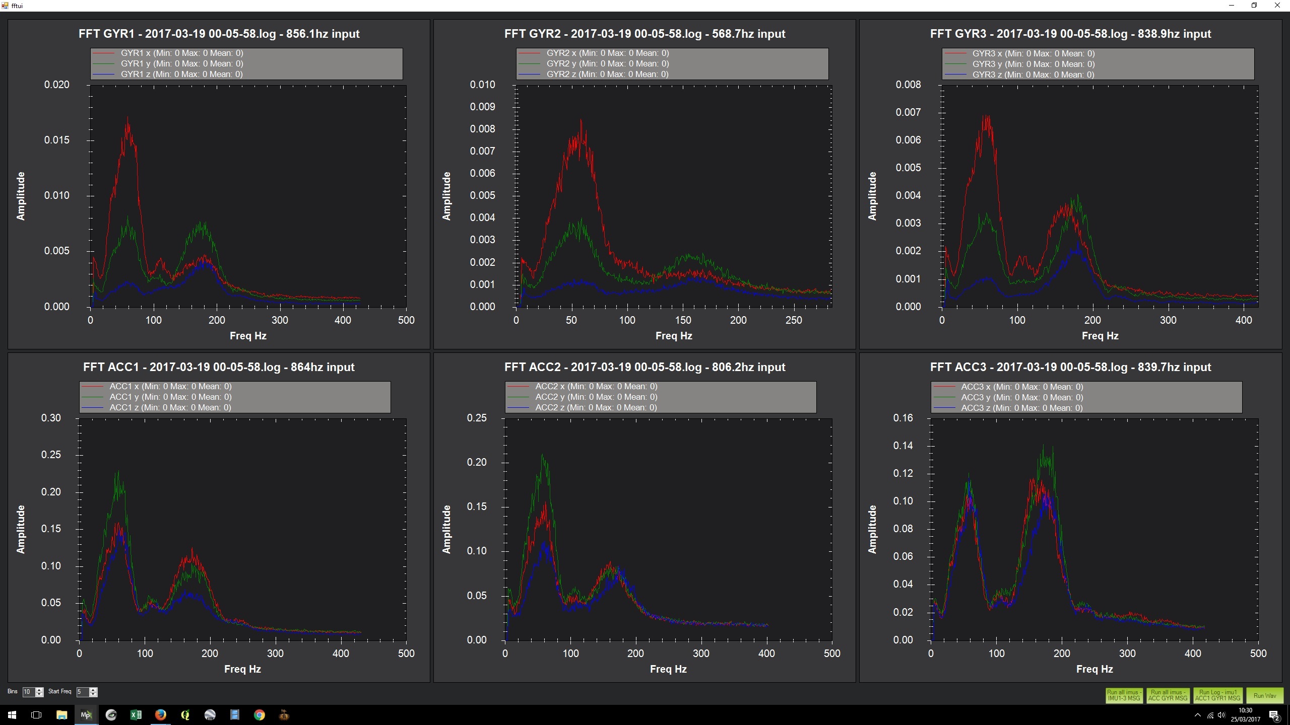
Here is an FFT of a 2 minute hover. ACC3 shows the undamped vibrations reaching IMU3, there are peaks at ~180Hz and ~60Hz. The amplitude of the peaks is 0.12-0.14. When comparing ACC3 to the ACC1 and ACC2 graphs, the 180Hz peak is reduced (by about half) but the 60Hz is amplified (almost double).

So it appears that the natural frequency of the Pixhawk damping system is around 60Hz. Harmonics of this frequency, particularly sub-harmonics, will also be less affected by the internal damping (15Hz, 30Hz, 60Hz, 120Hz, 180Hz, etc. etc.), and will add to the vibration at the natural frequency.

In a multirotor the vibration sources (props/motors) are not in phase with each other, but as the rpm changes, they might pass through moments of being in phase (or out of phase), which could cause moments of increased (or decreased) vibration.

B. What is the effect of these on flight?

In general vibrations cause problems with position estimation (accelerometers) and attitude (gyros). Severe vibrations cause obvious problems with erratic behaviour in flight. If the vibrations are not so severe as to interfere with the ability of the craft to fly, they can still cause problems in GPS assisted/automated flight modes. Poor position holding, causing the craft to drift in one direction or the other when holding position, is one symptom. Increased susceptibility to wind or turbulence causing unusual or hesitant appearing automated flight is another.

Hitting the frequencies or harmonics of the Pixhawk 2 can cause a sudden jump in vibration levels. For example, if the prop RPM in the hover is close to the natural frequency or one of its harmonics, flight characteristics may be mostly OK, but exhibit periodic divergences as frequency and phase relationships change. When a divergence becomes severe enough to get through the noise, the motor rpm correction will probably change the dynamic relationship and restore good control.

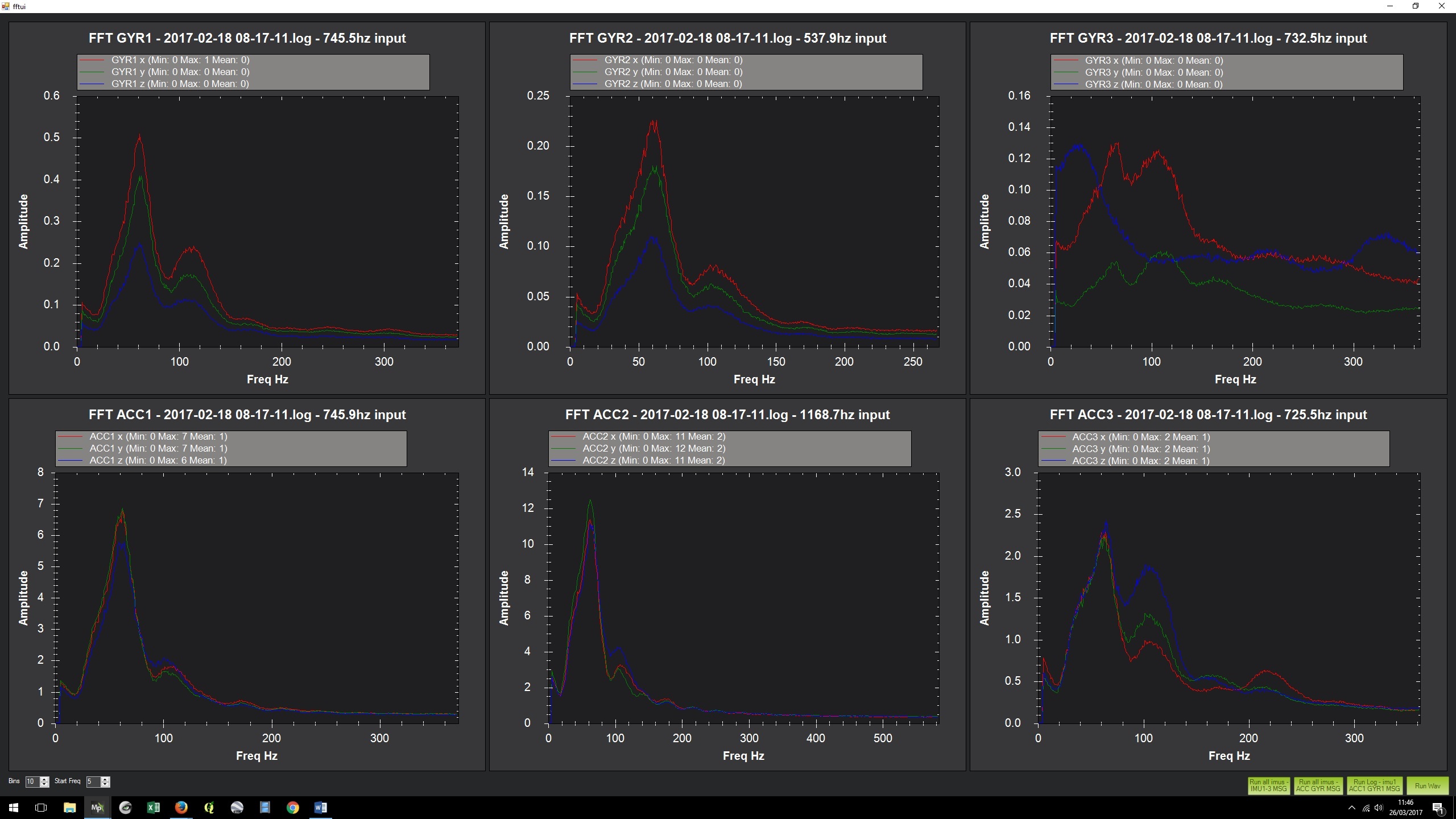
Here is an FFT of a fairly long flight – same model as the FFT above, but an earlier incarnation which was not flying in a confidence inspiring way

C. How can someone measure this on their airframe?

Using the FFT function in Mission Planner. To do this you need to:

  1. Enable full or high rate logging using the LOG_BITMASK parameter
  2. Carry out a test flight
  3. Download the logs
  4. Ctrl-F in Mission Planner to bring up the ‘temp’ menu
  5. Hit the FFT button and chose ‘run all imus – ACC GYR MSG’
  6. Compare the ACC/GYR3 results with the other two IMUs
    (The amplitude is relative, longer flights will produce higher numbers. Also be aware the scale will be different for each of the charts by default, this needs to be taken into account when interpreting the results)

D. If your airframe has vibration in these bands, what can be done to protect the system from this?

Propeller RPM, or possibly a resonance excited in the frame by the prop RPM, is going to cause these harmonic frequency related problems. If the frame is stiff enough, then changing the prop RPM is the simplest way to investigate or alleviate the problem. This can be achieved by changing the prop size, pitch or number of blades, or the all-up-weight of the model. If that cannot be changed enough to reduce the problem then an additional damping system could be used, chosen to be effective at the problem frequency.

13 Likes

Charlie drop the mic!

Thanks for the info Charlie - very informative

Great, thank you very much

foan tape, how to place that ?
between the arms and frame ? hard to understand.

So this was called a competition, who is the winner…?

1 Like