Im new here and not sure where to start.But im trying to turn led’s on and off with a switch on my TX .Im not having much luck.Im using a Pixhawk flight controller if it was an apm flight controller I could use a receiver controlled switch but not with Pixhawk.
This is easily done with a Pixhawk. You will need a MOSFET to take on the load of the LED’s. You can not drive the LED’s directly from the AUX pins.
By default pins 54 and 55 are set to digital output and will go from 0 volts to 3.3 volts based on a PWM value coming from the radio. Or you can control it with Mission commands.
Pins 54 - Aux pin 5 and 55 is Aux pin 6.
Need to know what kind of hardware you have and what type of LED’s you are you using.
Mike
Thank you so much for replying im pulling my hair out with this I can easily make it work on my quad with an apm flight controller but not the pixhawk.For hardware of course im using a pixhawk, I have installed a Turnigy receiver controlled switch that I want to control with a toggle switch on my TX My TX can output either PWM or PPM I have it set to PPM since im using a pixhawk.I also have installed a bec to the output rails on the pixhawk for redundancy.I will attach the hardware im usingThanks so much in advance for your help.All I want to do is be able to turn the led’s on and off with a switch on my TX
I’m using the Turnigy switch on backup and have used a few of these 5in1 Led Controller.
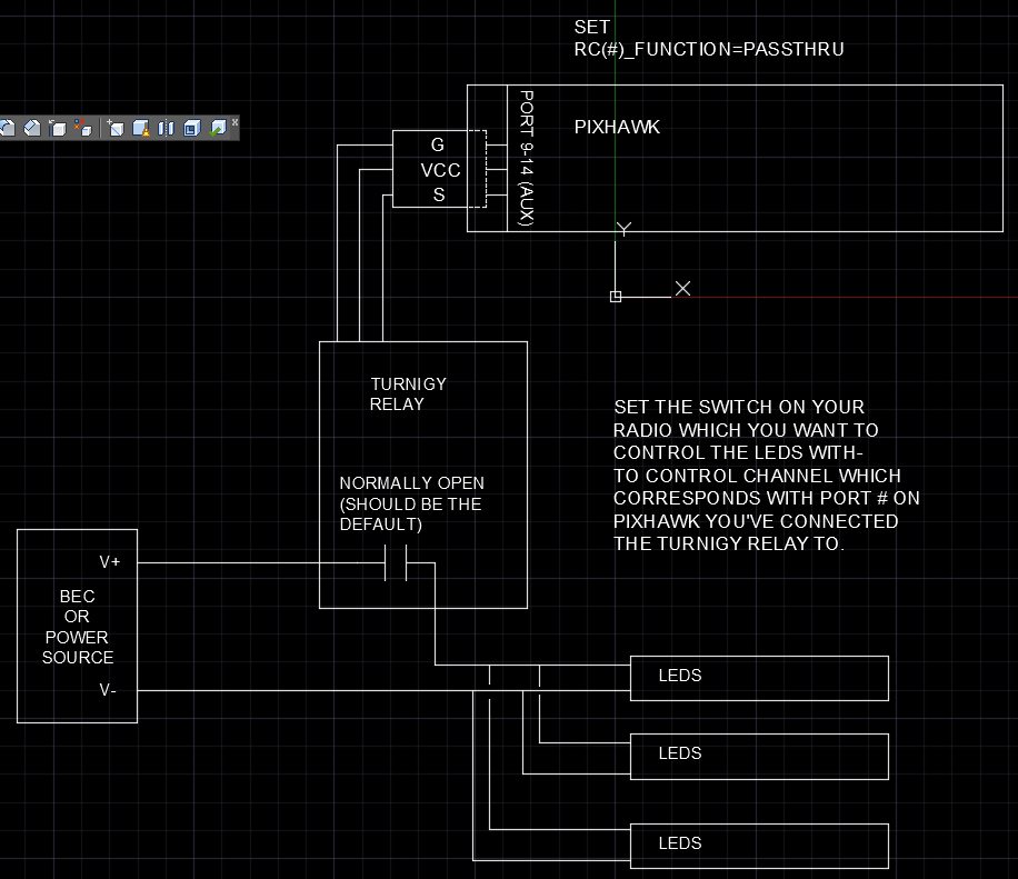
Simply run 1 leg of your 5 or 12v power to the leds into and out of the turnigy switch, connect it to any aux 9-12, map that to your reciever switch, and turn RC(aux port number)_Function to passthrough and it should work.
The 5in1 is a bit more complicated, only because the instructions suck. Basically you setup the same, but you need a 3 pos. switch, because the led control will do 3 functions - off, on, and lost vehicle/led flash. But it provides the voltage you need and you can hook all of your leds to it without worrying about a separate bec.
OK im clear on wiring it for 5v power.where you have me alittle confused is the aux9-12 what is that. I know where pins 50 -55 are on the pixhawk.and I know RC_ # Function is.
in other words this is where I get lost… connect it to any aux 9-12, map that to your receiver switch
and thanks very much for the help
Inputs 9-14 (pins 50-55) on Pixhawk are the “aux” ports. I don’t use 13 and 14 since they have relay capability, and that’s not needed here.
If you connect it to port 9 / pin 50, you set RC9_function to passthrough. Map the switch output your radio to channel 9 of pixhawk. On Taranis Mixer, channel 9 would be SC if you’re using switch C.
I used one of these: https://www.digikey.com/product-detail/en/alpha-omega-semiconductor-inc/AOI508/785-1457-5-ND/3603372
It will cost more for shipping then the unit itself.
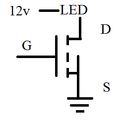
You connect the Gate to Aux pin 5 and the negative lead on the LED’s to Drain. The Source goes to ground and your done.
The unit will source I think 30A which is way over kill but it works.
Mike
Hey Mike Thanks for replying.Does that give me the ability to turn the led’s on and off with my TX.If so could you provide a little more info on how it works.
Thanks Alan
Sure, The relay Aux pin 5 goes to 0 volts and the Mosfet opens and shuts the LED’s off. When the Aux relay pin go to 3.3 volts the Mosfet is turned on and the LED’s come on.
In the Pixhawk you set it up as relay number 1 and can assign it to a switch. When that switch provide 1800 PWM it turns the relay on or if you use a Mission you can turn relay number 1 on with a command.
I have it set to Channel 9 on my radio which is attached to my Rudder D/R switch. When the switch is up it output 2000 PWM and when its down it outputs 1000 PWM.
In the Pixhawk I set CH9_OPT = 28 which is Relay 1 On/Off and RELAY_PIN = 54 to set what pin relay 1 is attached to.
Mike
1 Like
OK That makes alot of since to me now.Thanks very much for explaining it.Ill have to order the MOSFET’S Thanks again Alan
The transistor option works too.
If you already have the Turnigy relay - all you need to do is connect it - change the RC_function setting for the port you plug into, set the switch on your radio to control that RC channel, and it should work. When the switch (pwm) goes high, the relay closes, turning on your leds.
1 Like
im doing something similar but i found it was cheaper to get a 10a brushed speed controller than it was to get a 10a switch.
Sorry if I seem slow but this is new to me.Are you saying wire the Turnigy switch, plug that switch into aux 9 on the pixhawk I need to set rc9 function to pass thu and set a switch on my transmitter to use ch9 to operate the led’s
From the wiring diagram, that looks like what he is proposing.
Connect the servo lead from the Turnigy switch to Aux 9 (check signal wire is on the correct pin).
Run the +ve wire from the BEC through the Turnigy switch and then on to the +ve connection on the LED strip. Negative wire from BEC connects directly to -ve connection on LED strip.
Yeah sorry…there are 2 red wires on the turnigy which are the switch or contact. Connect your vcc+ to 1 of them and your led positive to the other.
Plug The Servo lead into any port 9-12 on the pixhawk. Set that port in mission planner to be passthrough.
Then set your transmitter switch to control that channel. A 2 position switch would be best and not momentary switch.
It shouldn’t take anything more than that.
That did it and so simple I just couldn’t figure it out Thanks to everyone